


Home Site Map - Techniques - Code and Drawings -
Blueprints
![]() The full set of house drawings you need and the most commonly used
symbols.
The full set of house drawings you need and the most commonly used
symbols.
Blueprint conventions
Worth sticking to the conventions
So that your drawings can be understood by others, particularly building officials and subcontractors, it is necessary to follow certain conventions in your official drawings. Personally I did all the incrementing of the house design in a light weight drawing package without worrying about official blueprint conventions and then I converted the drawings to official blueprints using AutoCAD. AutoCAD is very powerful, but making lots of changes in AutoCAD can slow you up if you are not an expert AutoCAD user.
Anyway, this page describes what's needed for your official blueprints and describes the conventions you should try to follow.
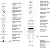
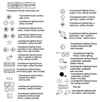
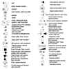
Typical symbols
Unfortunately there is not full consistency regarding what symbols are used on blueprints. Here are the symbols that I got by trolling around the internet and grabbing (thanks to the folks who put these online). Look through the symbols shown below and try to use one of those symbols rather than inventing your own.
My drawing process
It is worth looking at the info on my blueprint process that is here .
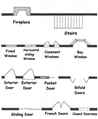
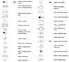
Structure Blueprint Symbols
Doors and windows etc
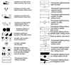
Plumbing Blueprint Symbols
Kitchen bath etc
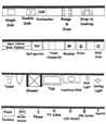
Bathroom etc
Misc 1
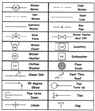
Misc 2
Pipes 1
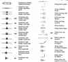
Pipes 2
Fittings
Valves 1
Valves 2
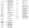
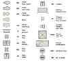
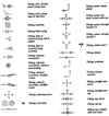
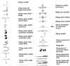
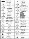
Electrical Blueprint Symbols
Basics
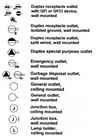
Fixtures 1
Fixtures 2
Outlets 1
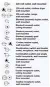
Outlets 2
Switches 1
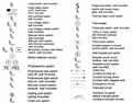
Switches 2
Low voltage
Blueprints needed for building permit submission
Exactly what is needed varies from area to area.
In my area (King County, WA) the requirements as to drawings are...
All plans should be a minimum of 18” x 24”, but it is best to use 36"x24". At a 1/4" to 1 foot scale the minimum text size in CAD should be 6" high. For drawings at a 1/2" to 1 foot scale the minimum text height in CAD is 3".
▪ Foundation Plans - (Required scale: 1/4” =1’);
▪ Floor Plans of Each Floor - (Required scale: 1/4”
= 1’);
- Indicate square footage of conditioned space, garages,
carports, outbuildings and decks;
- Designate use of each room or space. The number of bedrooms
should equal those on the
septic design approved by the Seattle-King County Department of
Public Health.
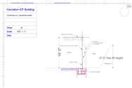
▪ Building Cross Section(s) - Usually through the
most complex area(s) (Required scale
1/4” = 1’);
▪ Elevations - (Recommended scale 1/4” = 1’)
for All Sides of the building;
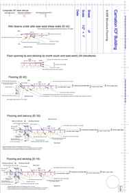
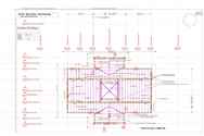
▪ Roof Framing Plans - May be indicated on the uppermost floor plan
(Required scale
1/4” - 1’);
▪ Floor Framing Plans - May be indicated on a floor
or foundation plan (Required scale
1/4” = 1’);
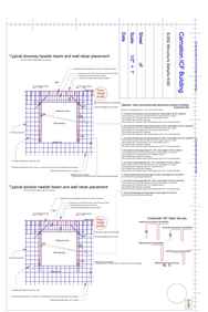
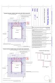
▪ Miscellaneous Structural Details - (Recommended
scale 3/4” = 1’); and
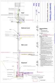
▪ Typical Wall Section - (Recommended scale 1/2” =
1’).
▪ Plot map
Drawing Sets Shall Be As Follows:
▪ Clear and with readable writing;
▪ Stapled together with plot plan as the first sheet;
▪ In order, with each page numbered consecutively;
▪ No pencil drawings; and
▪ Reproductions on substantial paper are required.
Additional Information Which May Be Required:
▪ Energy Code Compliance: Plans and specifications must comply with
the Washington State
Energy Code and the Ventilation Indoor Air Quality Code. Energy
forms are required for review
and permit issuance;
▪ For additions, include the floor plans of existing adjacent rooms.
Show location of windows and
their sizes and how they operate (horizontal slider for example);
▪ Engineering calculation and details for retaining walls other than
per Table 1805.5 of the IBC as
amended, as printed on the King County Residential Corrections
Sheet;
▪ Engineering calculations and details for beams, joists, trusses,
lateral loads (wind and/or seismic)
and special connections; (change formatting to be consistent);
▪ Site inspection by the Engineer/Architect of Record may be
required for special designs;
▪ Snow loads will be computed using King County DDES Snow Load
Analysis based on the
Snow Load Analysis for Washington, 2nd Edition, published by the
Structural Engineers Association of Washington;
▪ Flood Elevation Certificate delineating finished floor elevation
and FEMA 100-Year Floodplain
Elevation.
Blueprint Examples
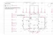
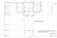
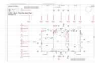
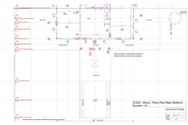
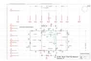
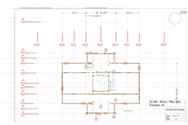
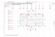
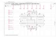
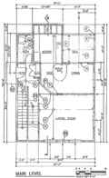
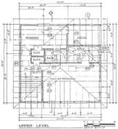
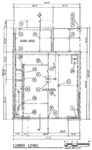
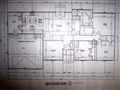
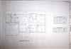
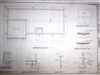
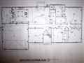
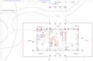
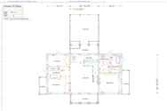
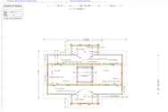
1) Floor Plan
The floor plan is what most people are familiar with when they are designing a home. It has the layout of the exterior and interior walls. The floor plan blueprints also need to include the dimensions for walls, rooms, wall thickness, windows and doors, kitchen and bath layouts, electrical and plumbing layouts, stairs, ceilings, and flooring. The main floor plan is an architectural blueprint of a top view that looks down on the home. You can see entryways, doors and walls. There needs to be one floor plan for each level, and that includes the basement and attic space. These floor plans usually have the floor joist placement and roof truss placement. The spacing measurements, nailing schedule, and beam schedule is usually included in this part of the plans.

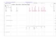
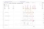
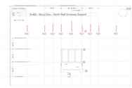
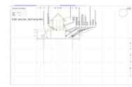
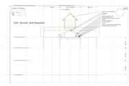
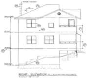
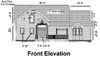
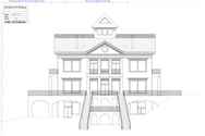
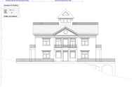
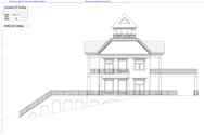
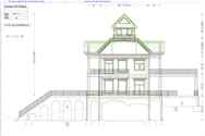
2) Elevations
This part of the plans help the inspectors understand the height of the outside of the house. It also shows the shape and size of windows, doors, trim, roof material and slope, and anything else that can help describe the outside building designs of the house.


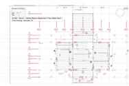
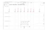
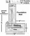
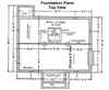
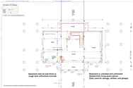
3) Foundation Plan
This blueprint shows how the foundation should be built according to the information from the soil sample. It shows how deep into the ground the footings will go and it gives the dimensions of the footings. It also shows the dimensions of the foundation wall and any columns or blocks used in the foundation. It also needs to show things like any vent locations in the foundation walls. The foundation plan includes details like frost levels, and slope or grade levels when necessary.
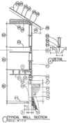

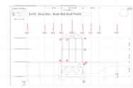
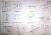
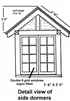
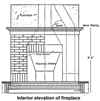
4) Details
This is a plan for some of the smaller things that have special build instructions. This is more for the subcontractors so they can get a good idea of the house design, but inspectors also like to know what's going on. Some of the details might include how a fireplace should look, stairs and handrails, molding and trim or just anything that is different from normal houses. The details sheet is part of the house blueprint package and is as many pages as needed. The details section is where the architect draws special details that might need special attention. Inspectors like to have vivid details.


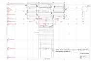
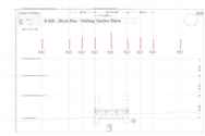
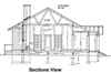
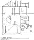
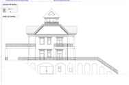
5) Sections and interior elevations
This part of the blueprint package shows how the parts of a building fit together and shows the important interior items that need special consideration.. Most of it is common sense, but sometimes walls, stairs, and things like fireplaces need a little extra explaining to avoid confusion. Like detail plans, the sections plans are more for the builder than the inspector, but they like to be kept in the loop. Usual items needing special attention are kitchens, bathrooms and fireplaces. Most house blueprints will include specialty interior items like these.

Notes to accompany blueprints
In addition to the drawings it is necessary to provide a comprehensive set of design and implementation notes. Some of these notes can be written onto the blueprint drawings, but others can be handled in a separate word processor document. Either way, there is a certain set of info that your local building department will want before they approve the plans.
For my area, King County require that the following aspects are
properly described and specified in the package of drawings supplied
with the building permit application...
1. Line of Structure Above - Particularly overhangs and cantilevers,
roofs, etc;
2. Crawl Space Vents - Call out typical size and quantity;
3. Crawl Space Access - Call out size of opening;
4. Type of Foundation - Example: concrete, wood or masonry – Call
out sizes;
5. Footings Continuous and Pads - Call out sizes;
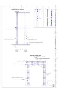
6. Columns/Post - Call out member size;
7. Bearing Wall - Call out for clarity;
8. Framing (Floor, Roof, Deck) - Show direction of layout, size,
species, grade and spacing.
(Example: roof rafters 2 x 10 H.F. #2 @ 16” O.C.);
9. Beams & Headers - Call out size, species and grade. Example: HDR
6 x 8 D.F. #1.
10. Ground-Cover - 6 mil. Polyethylene or equivalent;
11. Connectors - Beam to beam, post to beam, truss to beam, hangers;
call out size. Provide
detail and engineering for custom fabricated connectors;
12. Miscellaneous Structural Components - Show doubled joist,
blocking, etc.;
13. Spaces (Rooms) - Label areas; (Example: crawl space, closet,
bedroom, deck, etc.);
14. Heating System - Show location and call out size in BTUH or
other appropriate unit;
15. Stairs - Show Direction of Travel (up or down). Refer to Section
1009.3 of the IBC or
11.5.3 of the IRC;
16. Toilet Fixtures;
17. Mechanical Ventilation;
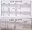
18. Doors - Show swing; if pocket door, show pocket area. Call out
sizes;
19. Sliding doors - Call out size;
20. Windows - Call out size. Indicate if fixed or operable. Window
sizes must meet minimum
requirements for light and ventilation. Windows in sleeping areas
must meet Section
R3101.1 of the IRC (or Section 1025 of the IBC);
21. Half Walls/Guardrails - Show height;
22. Decking - Call out type; if wood, call out size;
23. Line of Floor or Ceiling Openings - Call out stairs, elevator
shafts, laundry chutes or
dumbwaiters, etc;
24. Skylights - Call out size;
25. Attic Access - Call out size;
26. Fireplace - Install per manufacturer’s specifications. Chimneys
must extend 2’ - 0” vertically
above any structure within 10’ - 0” measured horizontally;
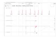
27. Ridges - Call out size and species of ridgeboard;
28. Hips - Call out size and species of hip rafter;
29. Valleys - Call out size and species of valley rafter;
30. Roof Framing;
- Trusses - Show direction of layout; call out spacing. Show and
label hip masters,
hip jacks, end jacks, girder trusses, hangers, bearing areas, etc;
- Conventional Roof Framing - Show direction of roof rafter and
ceiling joist layout; call
out spacing; and
- Show and label rafter ties, purlins, blocking, support joints,
bearing points and/or walls,
etc.
31. Smoke Detectors;
32. Concrete Foundation - 48” maximum unbalanced backfill; if
higher, submit engineering
calculations and details with stamp from licensed professional
Architect or Engineer;
33. Concrete Foundation With Cripple Wall - 4’0” maximum unbalanced
backfill restrained at
base by concrete floor; if higher, submit engineering calculations
and details from licensed
professional Architect or Engineer;
Obtaining A Residential Building Permit Bulletin 9
Bulletin 9 09/22/2008 Page 11 of 14
34. Slope of Roof - Rise and run;
35. Finish Roof Material - Call out type of roofing; specify
interlayment and/or underlayment;
36. Roof Sheathing - Call out size; indicate if solid or spaced;
37. Roof Members - Call out size; indicate if stick framed or
trussed;
38. Insulation Baffle - 1” minimum clear vented air space above the
insulation;
39. Eave Blocking/Attic Ventilation;
40. Gutter;
41. Overhang - Dimension;
42. Ceiling insulation - Call out R-Value;
43. Gypsum Wall Board (GWB) - Call out thickness;
44. Floor - Call out system. Indicate insulation and any level
changes. Example: 3/4” T&G
plywood decking over 2 x 10 floor joist (FJ) @ 16” O.C. over 1/2”
GWB;
45. Wall - Call out system;
(Example: Exterior - 1 x 8 bevel cedar siding over 1/2” plywood
sheathing over 2 x 6 studs
@ 16” O.C. with R-19 batt insulation on 1/2” GWB. Interior - 2 x 4
studs @ 16” O.C. with
1/2” GWB each side.);
46. Studs - Walls supporting two floors, roof and ceiling minimum 3
x 4 or 2 x 6 spaced @ 16”
O.C.;
47. For Foundations Supporting Wood, Extend Concrete 6” Above Grade;
48. Damp proofing and Waterproofing of Foundation Walls Enclosing a
Room
Below Grade – Refer to Section R406.1 and Section R406.2 of the IRC
(or Section
1807.2 of the IBC);
49. Foundation Wall - Indicate type of construction and size – Refer
to Section R305.1 of the
IRC (7’0”) or, 1208.2 IBC (7’6”);
50. Floor To Floor, Floor to Top Plate - Minimum 7’ 0” ceiling
height for IRC applications.
Refer to Section R305.1 of the IRC. (Minimum ceiling height for the
IBC applications is
7’6” – Section 208.2 of the IBC);
51. Garage Separation - Refer to Section R309.2 of the IRC. 5/8”
type ‘X’ GWB is used on
ceilings below habitable space. Garage to house walls, and garage
walls supporting
habitable space above shall be protected with a least ½ inch GWB;
52. Pressure Treated Sill - Call out size;
53. Anchor Bolts - Call out size and spacing. Example: 1/2” 0 x 10”
AB 6’ - 0” O.C.;
54. Reinforcing Bars (Rebar) - Call out size and spacing;
55. Drain Tile - Recommended and required in some areas;
56. Grade - Show on elevations;
57. Patios, Decks - Call out materials. Indicate distance of
finished floor from grade.
It is worth using the above as a checklist to make sure you have not
forgotten anything. When not building a wooden house some of
the questions will need a bit of interpretation and judgment, but
the list is still helpful in letting you know the types of info
required. If in doubt about whether some aspect needs to be
specified, it is worth specifying it. Too much info is better
than not enough and the plans inspector will appreciate it.
My blueprints
In my case I am the one building the house rather than a contractor so there is no particular need to indicate where things like electrical sockets and lights are installed. I just need to provide enough info to get a building permit.
List of drawings
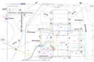
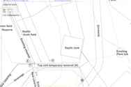
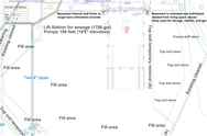
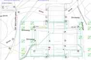
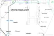
Full plot map
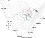
Plot map of build site


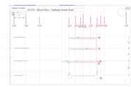
Art drawing - South
Art drawing - North
Art drawing - West
Art drawing - East
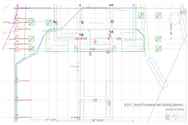
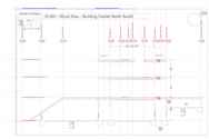
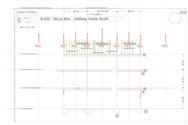
Basement floor plan
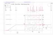
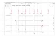
Main level floor plan
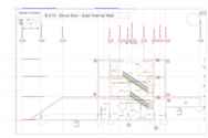
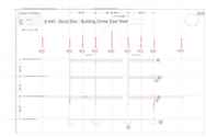
Bedroom level floor plan
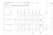
North elevation
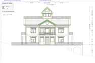
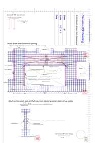
South elevation
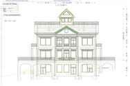
West elevation
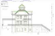
East elevation
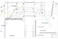
Foundation plan full
Roof plan
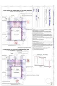
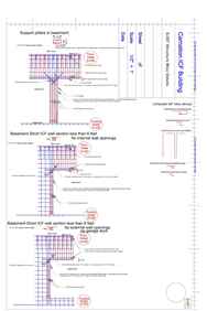
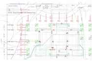
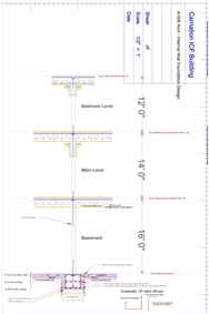
Wall and foundation design full
Wall and foundation design interior walls
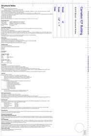
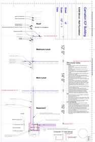
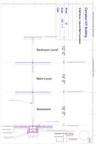
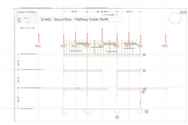
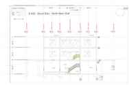
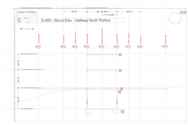
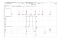
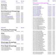
My structural engineering set of drawings
Here is the complete set of structural engineering drawings submitted for my house...