Home Site Map - Techniques - Structure -
Carnation Walling (ICF)
![]() An innovative poured concrete low cost wall forming system that provides
R36 wall
insulation.
An innovative poured concrete low cost wall forming system that provides
R36 wall
insulation.
Use Carnation Walling rather than traditional ICF
This page describes in detail the steps to use the Carnation Walling method to build a complete level of your house including the Carnation Flooring above that forms the concrete ceiling. This technique is repeated 3 times in the process of building a three story house such as mine.
If you want to use traditional ICF there's a page here that details the benefits if ICF, and a page here that describes suitable ICF blocks to buy. If you are using traditional ICF then here are the steps (but I urge you to follow the steps below instead).

ICF is great, but it has a negative in that some of the polystyrene is on the inside of the concrete wall structure. Building science tells us that it is better to have all the insulation on the outside of the concrete. This is why I use what I term "Carnation Walling". You can think of this as IFC (Insulation Formed Concrete) rather than ICF (Insulated Concrete Forms). Using regular sheets of EPS is also much less expensive than buying ICF blocks.
I do my own concrete wall forming using regular EPS sheets. These are a commodity item and as such there is competition between suppliers that keeps the price down. "Carnation Walling" is a *method* of building rather than a proprietary product. The method puts all the insulation on the outside of the concrete and relies on removable re-usable plywood to hold the concrete on the inside. The details on this home made ICF system and the building science behind it are here and you should read this in detail before proceeding.
I am using 6" thick EPS sheet as the main layer of EPS with an additional 2" thick EPS sheet glued with foam adhesive to the outside with staggered joints to avoid there being any exposed joins for concrete to leak through. On the inside Carnation Walling uses a thin layer of smooth plywood and a thicker layer of construction grade plywood with staggered joints.
Get everything marked up on your CAD drawing
Make your CAD drawings correct
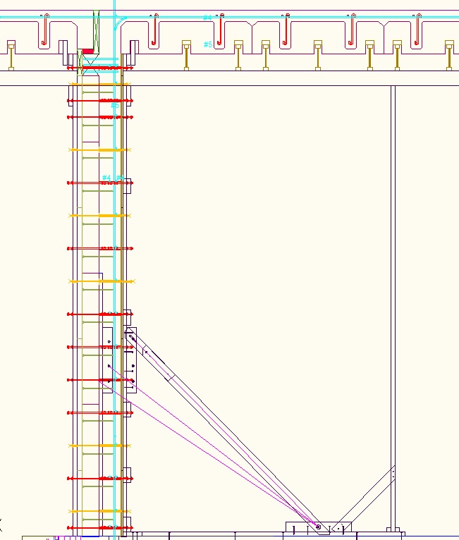
Things will go wrong very quickly if you measure and cut as you build. All cutting and positioning of things needs to match exactly with the CAD drawing. If something does not match then find out why before proceeding. The CAD drawing needs to show all the tie positions through the concrete, all the bracing, including where the angled bracing attaches to the floor. Getting the CAD plan drawing correct is very important. With things like bracing it is sometimes necessary to joggle things about a bit to get everything to work out and it is so much easier doing this in a CAD app rather than on site.
Allocate plenty of time to updating your CAD floor plans with this info. Read through the steps below and as you imagine yourself doing each step, and update the CAD drawing. In your mind, build it in CAD first.
Here is a drawing for a very simple building (suitable for a plant potting shed in the yard)...
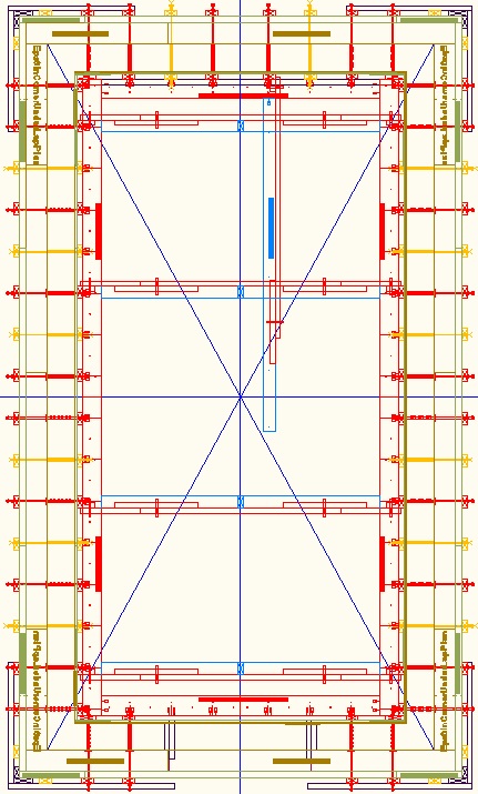
It does take a bit of practice and experience to allocate the EPS sheets (and plywood sheets) to the desired building footprint, but I have tried to write down the rules below. If you need me to do you a CAD drawing for your house then I can, but a fee will be involved as it is quite time consuming.
Add Wall section center markers
Start by drawing the blue lines to divide the building into 4 quadrants. The halfway measurements are from the outside of the concrete wall (the outside of the concrete is the reference line). However complex the building, there should be only one north/south east/west cross, centered on the center of the building. You start figuring things out from the center of the building and work your way outwards. Add-on concrete rooms round the outside are handled separately rather than having their walls divided in half.
Diagonal lines for squareness
Draw the diagonals to the wall reference so that when on site you will be able to check the right-angles of the walls drawn on the slab are correct.
Add-on concrete rooms
If there is a U shaped piece of concrete wall used to add-on a room, the join to the main building will not anyway be able to use standard blocks, so there is no point in calving up the room with wall section center points. Just use the outside concrete of the convex corners of the U as the reference when doing the 1' markers described below. The room will typically still be divided in the other dimension by the building's divider cross. I use this technique for the east and west concrete sections of the house and also the add-on portico bases in the basement.
Internal walls
It is best to treat internal concrete walls as external walls within the internal room that they form. Use the outside edge of the concrete as the reference for the 1' markers.
Treating internal walls as if they were external rooms means that other concrete rooms are handled as add-on concrete rooms.
Internal walls do not use any EPS. They have the twin plywood on both sides. There is a nailed down kicker board on both sides.
It is only necessary to have angled bracing on one side of internal walls and it is best to put that bracing on the inside of the internal room that they form.
Odd and even 1 foot markers
Draw the 1 foot markers starting at the convex corners of the outside wall concrete of the inner-most concrete room. Identify the 0, 2', 4', 6', etc points as "primary" points (make those marks red). Make the markers at 1', 3', 5', 7', etc be "secondary" markers (make those marks blue). Follow the same process (starting with outside corners) when you add the markers along the wall for the add-on concrete rooms.
Concave corners
In terms of the wall tie hole pattern there is no special handling for a concave corner because of the concept of add-on rooms. The pattern will have come from the outer convex corner and the EPS sheets just get cut at the required point to fit into the concave corner.
Angled wall braces
Angled wall braces should only ever be at the primary markers (the red markers). Typically they go every 4 or 6 feet. You can move them to different primary markers and that is sometimes useful to avoid clashing with angle braces from the adjacent wall.
If there is a clash between angled braces it can be handled by an offset angled brace, but that is not as good as offset angled braces are not as easy to adjust.
Sometimes you can leave out an angle brace if the EPS will be overlapped with a perpendicular piece of EPS that will naturally hold it vertical. Just because there is no angled brace at a particular location does not mean that there isn't still a vertical 2x4 baton that is held vertical by the horizontal bracing.
EPS at building centers
At the building center cross points (as the blue cross intersects a wall) it is necessary to arrange for the joints to be next to a suitable odd numbered (secondary) 1' grid point so that it has a vertical 2x4 over the join. It is necessary to use custom blocks. Different secondary marker points are chosen to join the 6" EPS compared with the 2" EPS.
Unless the center point happens to fall on a marker point (unlikely) then the drill pattern changes when going past a building center point. It is good to have at least one column of wall ties each side of the joint, so that means custom drilling of hole columns is necessary. You still will want to keep to the rule of the first column of holes being 1" from the edge (offset towards the corner). You can still use a jig to drill the holes by flipping the sheet over in the jig and using the other end as the reference.

If the distance that needs to be spanned between standard blocks exceeds 8' (the max length of a sheet) then you butt the join 1" from a red primary marker. This avoids it being on a join for the row above. For a very long span you might need two joins next to red primary markers.
12" cavity corner wall tie offset
At corners in the case of 12" cavity walls it is necessary to adjust the wall tie placement by 4" relative to the 1' regular grid. This means the holes in the EPS need to also be offset by 4" (and this is supported by an extra optional column of holes in the drilling jig). Also the the horizontal bracing is 4" shorter at the corner end.
2nd and 4th EPS row version
The initial working out of EPS sheet lengths is done for the base row of EPS that goes on the slab. This is also the configuration used on the 3rd row. The 2nd and 4th row use a different configuration so as to produce a staggered brick pattern. It is necessary to do a different version of the CAD drawing that shows the EPS sheet lengths for the 2nd and 4th rows. Everything else about the CAD drawing (including all the bracing etc) all stays the same.
Bracing for bucking
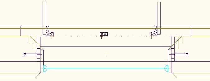
Bracing is used to support the inside edge of the window bucking long before wall concrete is poured and even before the wall rebar is added.
There is always an internal vertical 2x4 baton near each side of a window or other wall opening. It attaches to the Cavity Bucking top and bottom using 3" wood screws (and some wood blocking for added strength). The internal vertical 2x4 batons are always on the odd numbered secondary 1 foot markers so they don't interfere with the wall bracing. They will likely not be symmetrical on the window but that's ok. Make the internal vertical 2x4 batons offset in the direction determined by the nearest corner of the complete building.
The internal vertical 2x4 batons for the windows are in addition to the internal vertical 2x4 batons for the walls. When doing the CAD drawing, add the batons and angle bracing for the wall openings in addition to the angled bracing that you will already have added for the wall using the normal rules. The presence of windows, doors, or other wall openings does not reduce the amount of wall bracing or its placement.
Between the two ends of the bucking add internal vertical 2x4 batons at all the secondary locations. This is to help support the weight of the bucking. Note that the bucking needs to be supported even while the wall bracing is not fitted or is in the concrete cavity position. The bracing for the bucking starts in its final position rather than in the concrete cavity position.
Elevations and window door openings
In the CAD app, onto the elevation drawings, copy on the standard block elevation library shapes. Use all the rules described above. Make sure it all matches with the plan drawings. Where a standard block will not fit, draw the cut shape with regular lines (using the 2" or 6" EPS CAD layer). Draw on the window and door openings. Do it for the 6" and 2" EPS.
Once all done, turn off all layers apart from the 6" EPS layer and then turn off all layers apart from the 2" EPS layer.
Real CAD example
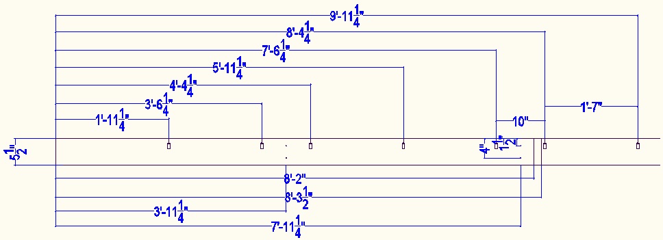
Here is the CAD drawing for my basement level. It is quite difficult to remember all the rules stated above so it is not a bad idea to take this drawing as a starting point and modify for your own particular house design. (It's better looked at in the CAD app and that also let's you get dimensions of the EPS sheets.)
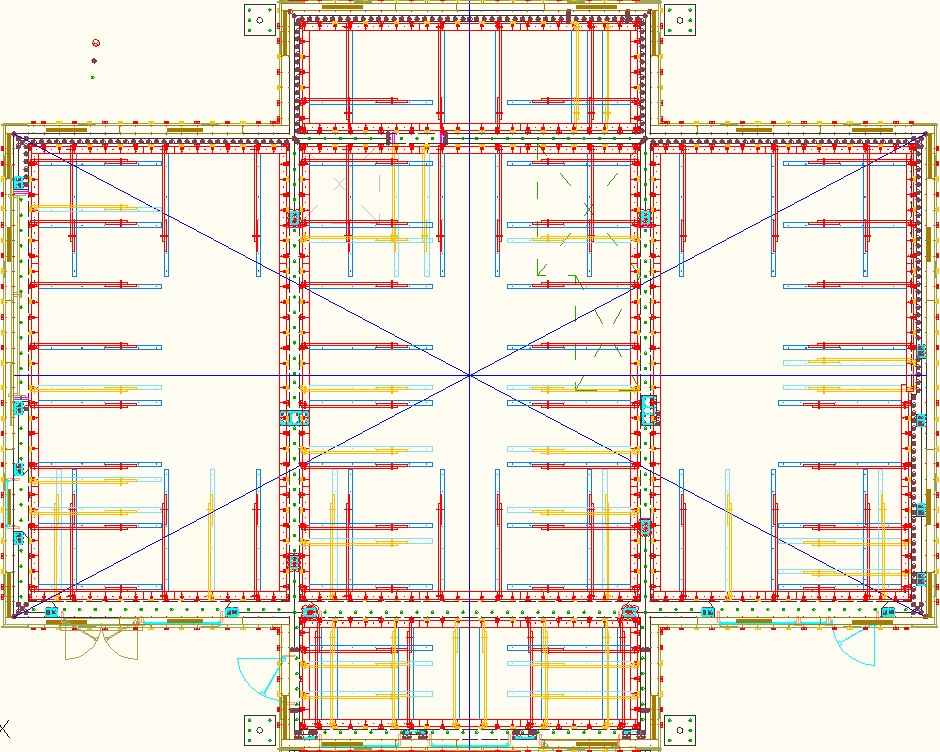
Note that the EPS sheet lengths shown are for the base row of EPS that goes on the slab and also for the 3rd row. The 6" EPS is 4' high and the 2" EPS is 2' high on the base row. The row above has different lengths in order to produce the staggered join pattern (and both the 2" EPS and the 6" EPS are 4' high sheets).
Here is the CAD version for the 2nd and 4th rows (it's better looked at in the CAD app and that also let's you get dimensions of the EPS sheets).
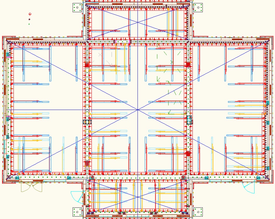
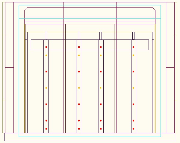
Here are the CAD drawings that show the window and door openings for each elevation as well as the tie rod positions.
South Elevation


West Elevation
East Elevation
North Elevation
Buy the materials
The house is built one story (ie one level) at a time, with the concrete ceiling of the house level being done at the same time as the walls for that floor. For each story you need to buy enough 6" and 2" thick EPS sheets for the walls including the portico bases and also buy the Carnation Flooring EPS for the ceiling above. Here's the list of parts needed...
EPS sheet (6")
EPS sheet (2")
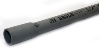
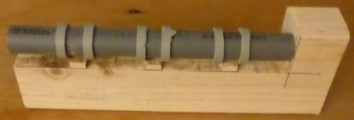
1/2" electrical conduit (10'
lengths)
3/4"
electrical conduit (10' lengths)
3/8"
threaded steel rod (10' lengths)
3/8" steel zinc plated nuts
3/8" large steel zinc plated washers (about 1" diameter)
1.5" nylon washers with 3/8" hole
8'x4' plywood 15/32" thick
(Nominally 1/2")
8'x4' plywood
3/16" thick (Nominally 1/4")
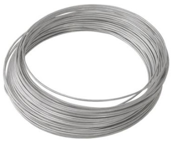
Galvanized wire 14
gauge
1-1/2" small head nails
3/4" large head nails
Foam adhesive
2x4
lumber
Turnbuckles
Rebar cable ties
11" (120 lb)
Basalt
Rebar
Carnation Flooring EPS cut forms
Mark house outline with felt pen
Mark outer edge of wall concrete
The OUTER edge of the WALL CONCRETE is the reference and this needs to be as per your house CAD drawings. This is the INNER face of the EPS. The EPS outer edge cannot be used as a reference because it overhangs the concrete slab.
Getting the dimensions from your CAD drawing, accurately mark the position of the outside of the wall concrete all the way round the house outline using a sharpie felt pen on the concrete slab. (For upper floors, the term "slab" refers to the top of the concrete floor of the house level beneath.)
The outer edge of the wall concrete (inner edge of the EPS) is an important reference line, and everything is based off that, so it needs to be accurate. Check the right angles by measuring the diagonals across the rectangle. The diagonals need to be exactly the same and the distance should also be the exact measurement that your CAD drawing says it should be (if not then find out what's wrong before proceeding).
Hopefully the wall rectangle will also properly relate per the CAD drawings with where the key notch has been formed in the slab.
For internal walls, the outside wall concrete is the concrete edge farthest from the building center.
Mark wall section centers and 1 foot grid
The positioning of the EPS sheets and bracing is all done from the convex corners of the wall concrete reference line. You work away from the corner until you get to either the center divider point of the house or a concave corner.
Mark with a sharpie felt pen along the outside of the wall concrete the points where the quadrant divider cross line intersects with the wall. These points should also of course be on your CAD drawing.
Measuring from the convex corners of what will be the wall concrete (ie the reference line), put a felt pen mark every 1 foot. Make the even numbered ones (the primary ones) one color (I use red). Make the odd numbered secondary points a different color (I use blue). The marks give the positions of the wall ties that go through the concrete and the possible positions of EPS (and plywood) joins (minus 1 inch). The marks should exactly mimic the marks on your CAD drawing.
At corners in the case of 12" cavity walls it is necessary to adjust the wall tie placement by 4" relative to the 1' regular grid. Again this should be shown on your CAD drawing.
Nail down inner 2x6s
The position of the inner 2x6s depends on whether it is an 8" concrete wall or a 12" concrete wall at each particular location.
The inside face goes 1.5" towards the center of the house relative
to the edge of where the plywood will be (the plywood edge closest to the
inside of the house). Relative to the sharpie felt pen drawn reference
line the distance of the edge of the 2x6 that is closest to the
center of the wall is...
Wall concrete
thickness (8" or 12") + 1/4" (thin ply) + 1/2" (thick ply) + 1.5"
(vertical 2x4s)
For an 8" cavity wall the distance is 10-1/4"
(14-1/4" for a 12" cavity).
Note that the plywood sheets are actually slightly thinner than the nominal thicknesses. This means that the concrete is marginally thicker than the 8" (or 12"), but only by 1/16" + 1/32" = 3/32" so it is of no consequence.
Mark the position of the inner line accurately with a felt pen (joining up your measured marks with a long ruler). Check that this accurately relates to the CAD drawing and that you haven't accidentally made it an 8" cavity where it should have been 12".
For internal walls, you will add nailed down kicker boards on both the outside and inside of the wall.
Make kicker planks
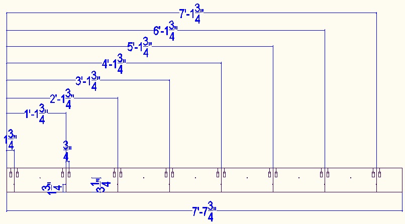
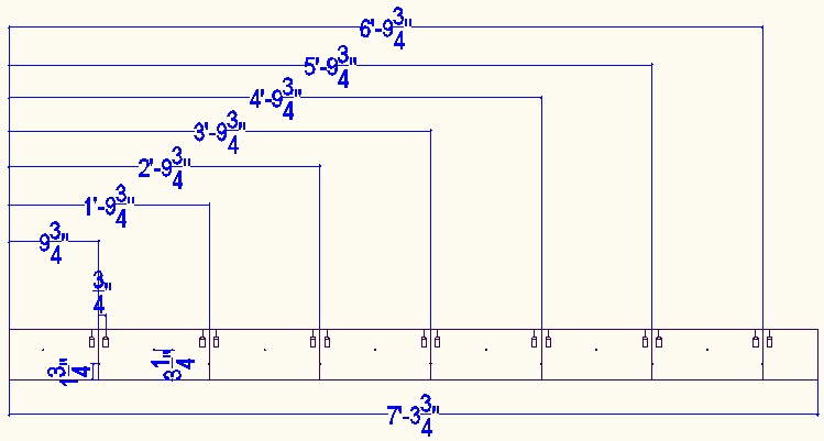
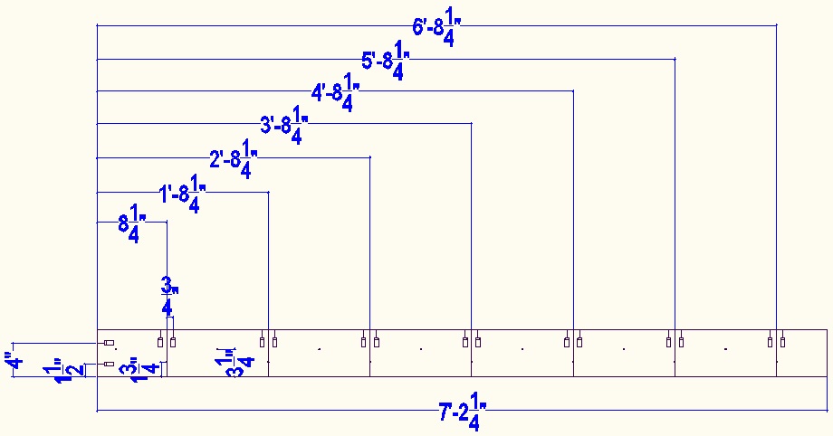
These are made from 8' long 2x6 lumber (ie 1.5" x 5.5"). Depending on whether it will be an over-lap or an under-lap at the corner, the length of a corner piece (for 8" cavity walls) is either 7' 7-3/4" or 7' 2-1/4".
In the case of a 12" cavity it is 4" shorter at the end that goes into the corner.
Mark the 1' grid positions along the length of the plank. Depending on whether it will be an over-lap or an under-lap at the corner, the first mark will be at 1-3/4" or 8-1/4". It is good to also number them so you can easily tell the even numbered (primary) from the odd numbered (secondary). 0 is the outside edge of the concrete at the corner (so is not on the kicker board) and then 1, 2, 3, etc. In the case of a 12" cavity, the first marker on the kicker board is 2.
Holes of 5/32" diameter are drilled (using a drill press) to make the nails go in straight. The holes are at the 1' markers at 1-3/4" from the outside edge and half way between the markers at 3-1/4" from the edge closest to the inside of the building.
For attaching to the in-cavity spacers, and then later the vertical 2x4 batons, drill TWO Kreg angled holes from the 2x6 kicker planks 3/4" either side of the 1' grid markers.
I use the Kreg Mini jig in a wooden jig to hold it the right distance from the edge and to make it big enough to hold down without bothering with a clamp.
When drilling the Kreg holes it is necessary to know where the kicker board will be in the building, ie which way up it will be. This of course lets you drill the holes from the right side and on the right edge.
Here is the corner over-lap case for an 8" cavity...
Here is the corner over-lap case for a 12" cavity...
Here is the corner under-lap case for an 8" cavity...
Sometimes, eg for my potting shed, the distance to the wall half way crossover point is very short. In this case it is good to make the plank twice the length and make it a mirror image of the hole patterns. In the drawing below, the dotted line shows the wall half way crossover point.
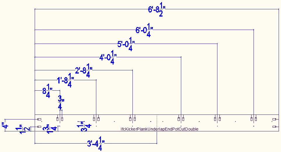
Here is the corner under-lap case for a 12" cavity...
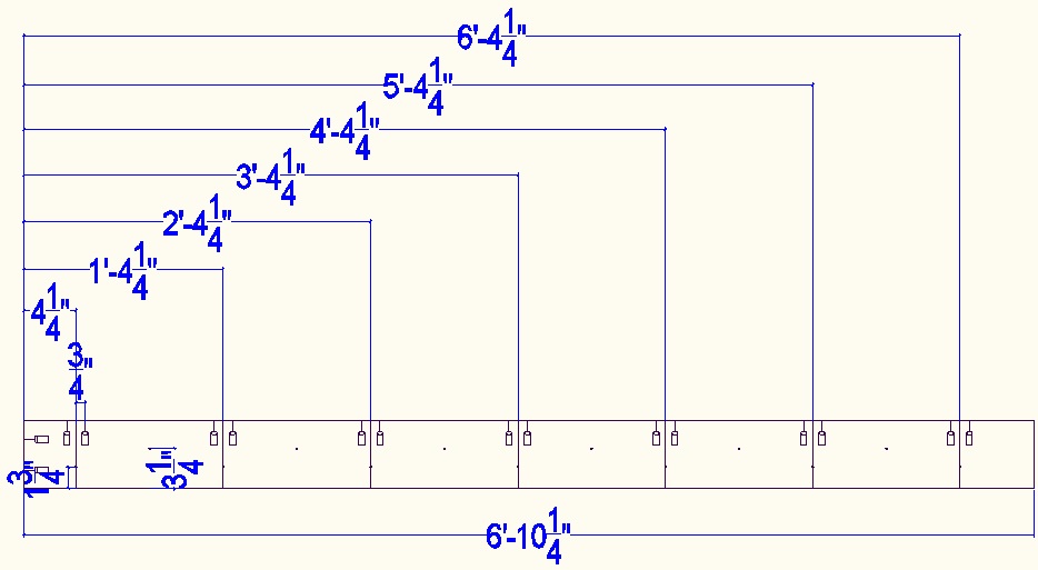
If the corner pieces are longer than half the wall section length then cut them at a marker+6" point. When not at a corner, the kicker planks are some integer number of feet long with the first of the 1' markers 6" from the end.
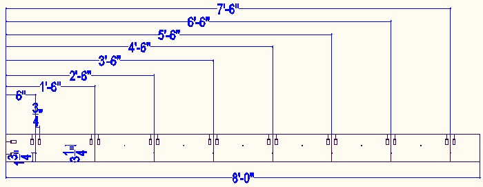
At the building center crossover points, the kicker planks typically meet at the center with the Kreg holes being measured from the different ends (because the wall tie hole pattern changes as you cross a house center cross point).
Paint the planks with red wood preservative paint .
Nail down kicker planks
Once you are sure, nail the kicker planks to the concrete, flat side down and with the wall facing edge accurately on the inner drawn sharpie felt pen line. Use the drilled holes for the nails. You will need the most powerful caps in the gun to penetrate the concrete.
On internal walls there are kicker boards on both sides of the wall.
Make Vertical 2x4 batons
The length of inner batons and external batons when doing a concrete
lip (see later for details of concrete lip) should be...
House story height - 2' 3-1/2"
For my 16' basement (that has a concrete lip all the way round the outside) the batons are all 13' 8-1/2" long. For my potting shed they are only 7' 8-1/2" on the inside.
External batons when not doing a concrete lip should be the house story height. The external vertical 2x4 batons for my potting shed are 10' as there is no concrete lip. If not doing a concrete lip, you can actually use vertical 2x4 batons on the outside that are higher than the wall height if you want to avoid cutting your long batons.
You need them to be the right length to support the Carnation Flooring so it works out best if you start building with the highest ceiling areas and then cut the batons shorter when you re-use them on other house levels. Cut the height off the bottom so you do not have to re-use screw holes. They should have pre-drilled 3/8" holes for the wall ties. It is convenient to use a Kreg stepped shoulder drill to avoid having to drill a pilot hole.
If you only have 8' long 2x4s then you can potentially join them using 1.5" square splints on each side, but it is obviously more work and not as good. You cannot on the internal batons use eg 2' lengths of 2x4 on the flat to join the two because that would get in the way of the horizontal bracing.
Draw lines across to show which holes are primary holes, ie the X'9" holes.
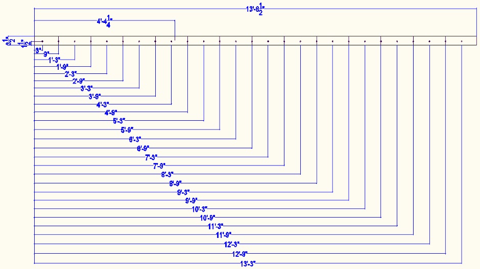
The face-on 2x4s have 3/8" holes for 3/8" threaded rod. These are positioned from the bottom at 3", 9", 1'3", 1'9", 2'3", 2'9", 3'3", 3'9", 4'3", 4'9", 5'3", 5'9", 6'3", 6'9", 7'3", 7'9", 8'3, 8'9, 9'3", 9'9", 10'3", 10'9", 11'3", 11'9", 12'3", 12'9", 13'3".
Put the holes 1.5" from the outer edge, except for the "right in the corner" case where the holes are centered (ie 1-3/4" from the edge). Make about half the batons measuring the 1.5" from one edge and half from the other edge, although aside from the markings it does not really matter as they are reversable. Use a drill press to get the 3/8" holes square and perpendicular.
Put a mark at a height from the bottom of 4' 4-1/4" so if you need to add angled bracing you will know where it goes. This line will align with the bottom of the edge-on 2' long 2x4 piece.
Put a mark on the bottom end to show the position of the column of holes. This is used to align the bottom with the 1' marks on the kicker board.
Try to use straight 2x4s but if they are slightly warped then make them bow towards the concrete. This is just for consistency and in practice the wood will get held straight by the surrounding bracing.
As with all other bracing parts, paint with red wood preserving paint .
Vertical batons are required on both sides of the wall. The pair of batons is every 1 foot along the wall. You need lots.
In my case as I have a sawmill, I use timber from my forest for the vertical 2x4 batons, but it does have to be allowed to dry for 6 months to a year before use. Avoid mixing kiln dried wood with sawmill cut wood for fear of having different shrinkage rates.
Make and fit wall angle bracing
It is necessary to angle brace a concrete wall (both an ICF wall and a Carnation Walling wall) to hold it straight and true while the concrete is being poured and is setting. Without angle bracing, the wall may also go off vertical. There are various manufacturers of ICF bracing systems, but they are expensive to buy and expensive to rent. The other problem with renting is that you are working against the clock, whereas I prefer to take my time to get the concrete walling exactly right and so that I have time to make all the conduit openings etc.
My solution was to design my own low cost angle bracing system using regular 2x4s.
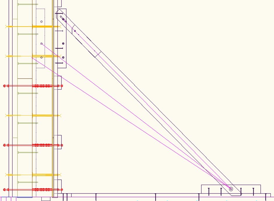
The bracing with the 45 degree 2x4s is used on the inside of the building. On the outside are attached vertical face-on 2x4s. In the case of the external vertical 2x4 batons they do not need any 45 degree 2x4s because they are attached via the wall ties to the internal vertical 2x4 batons that are held vertical by the angle bracing.
The average length from hole to hole of the angled bracing is 8' 0-1/2", but the length is variable by +/-1.5".

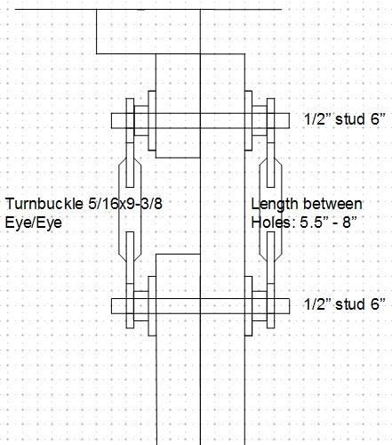
The vertical bracing is installed about every 4 or 6 feet, but that spacing can vary in plus or minus 2' increments to accommodate where the window and door openings are. Angle wall bracing only ever goes on primary 1' markers.
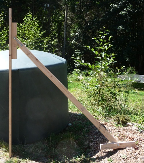
Prior to pumping the concrete into the ICF wall, the turnbuckles are used to get the wall vertical and the bolts are tightened to fix everything in place. Immediately after the concrete has been poured (before it sets) you then go round and re-adjust whatever bracing is necessary to ensure that the wall sets perfectly vertically.
Edge-on pieces
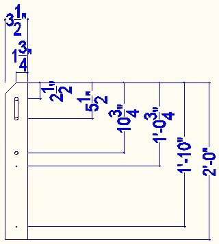
Edge-on 2' long 2x4 lumber is attached to the vertical face-on lumber and provides a 1/2" hole that is 6 foot above floor level. For Carnation Walling there is also an additional 1/2" hole at 5' 2-1/8" above floor level (8" cavity) and another at 4' 8-1/2" above floor level (12" cavity). Measured from the bottom of the 2' long 2x4 lumber these holes are at 4-1/4", 9-7/8", and 1' 7-3/4". It is good to use a Kreg HD 1/2" stepped shoulder drill bit to avoid having to pilot drill first. The bottom of the 2 foot 2x4 is the reference and it is ok if the length of the 2' 2x4 is fractionally short so you can make 4 from an 8' length of 2x4.
The extra 1/2" holes are to support the vertical 2x4 batons when they are temporarily installed where the concrete will go.
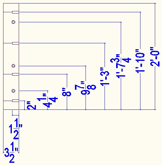
The holes in the edge-on 2x4 are clearance drilled (2" of wood left) so that they can be screwed to the face-on 2x4. Use a 6" long 3/16 drill first to drill all the way through and then drill with a depth set 1/2" drill.. Don't screw from the other side or you will not be able to easily add or remove the edge-on pieces with the vertical batons in place. From the bottom of the 2' long 2x4, the holes are at 2", 8", 1'3", and 1'10".
Screw on the edge-on piece to the vertical 2x4 baton where angled bracing is needed. The bottom of the 2x4 piece goes 4' 4-1/4" from the bottom of the vertical 2x4.
Angled bracing
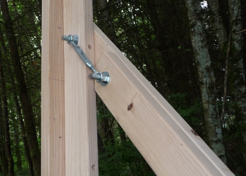
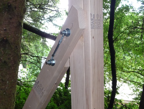
The edge-on vertical 2x4 has an approximately 45 degree 2x4 attached using a bolt in a slot arrangement. The slot is what allows the vertical-ness of the wall to be adjusted. Half inch zinc plated threaded rod (6" long) is used on both ends of the slot moving parts. Turnbuckles can be fitted between these and are used to set the vertical-ness of the wall. The nuts on the half inch studding can then be tightened in position and then the turnbuckles are no longer required (saves the cost of lots of turnbuckles).
Some angle braces are assembled with a right hand configuration and some with a left hand configuration. This should be shown on your CAD drawing.
Edge-on base pieces
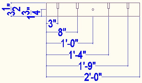
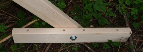
The bottom of the 45 degree 2x4s are bolted to 2' long pieces of 2x4. The holes (that are 3/16" but bored to 1/2" to leave 2" of wood) are at 3", 8", 1'4", and 1'9". If the 2x4 is fractionally less than 2' long that's fine but mark one end as the reference.
The 1/2 hole for the angled bracing is in the middle, ie 1-3/4" from both sides (and 1' from the reference end of the 2' 2x4).
These edge-on pieces are screwed to longer lengths of 2x4 that are nailed to the concrete slab.
Make the nailed-down on-flat base pieces

These can be made from regular 8' long 2x4s. If the distance between walls is small then the base pieces need to be shared with the opposite wall. The base pieces need to be nailed to the concrete floor using the pilot holes to get the nail to go in straight.
The base pieces extend horizontally all the way to the nailed down 2x6s to help ensure the 2x6s cannot move with wet concrete pressure. It is useful to have a Kreg jig hole at the end for attaching to the kicker board so it is held in place while being nailed down.
As with all other bracing parts, paint with red wood preserving paint .
Put a mark at 4' 4-1/2" so you know where to screw on the edge-on base pieces.
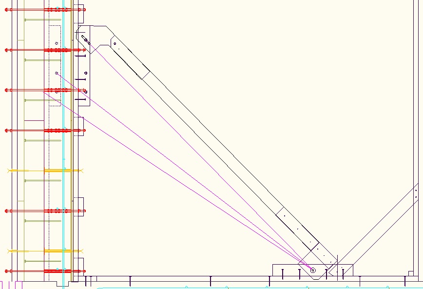
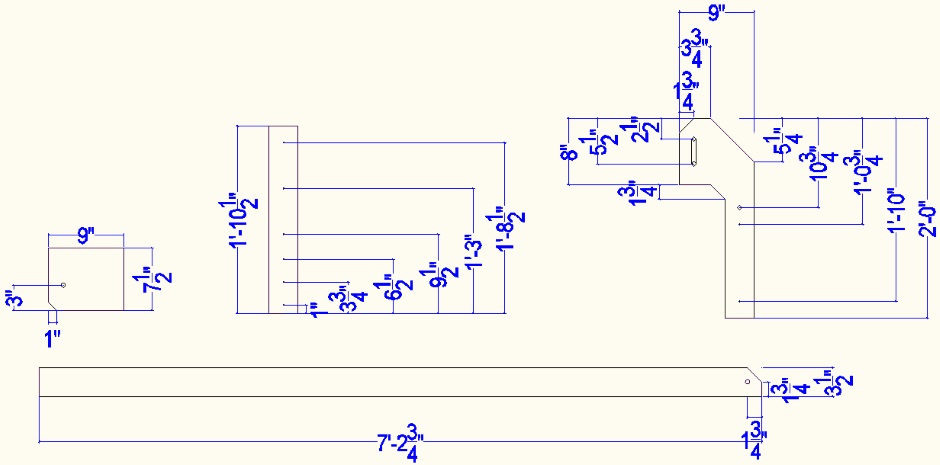
Offset angled bracing
To handle the corners it is sometimes necessary to offset the angled brace to miss the angle brace going in the other direction. The offset assembly needs to be well glued together to withstand the offset forces.
An offset angle brace does not work as well as a regular angle brace because you cannot use a turnbuckle. You have to nudge it to get the wall vertical and then do up the 1/2" nuts.
Weatherproofing
Paint all the bracing with red wood preserving paint because the bracing will get rained on and you want to be able to reuse the bracing on other floors of the house.
Establish angle brace positions
You need to have the brace positions worked out and drawn on your CAD drawing. You will get dimensions from the CAD drawing and transfer them to sharpie felt pen marks on the slab.
The rule to follow when placing the vertical 2x4 batons is that the 1-3/4" edge (from the holes) goes towards the corner (away from the center of the building quadrant divider cross). This better overlaps with the EPS joins that are 1" from the holes.
For a small building that shares the nailed down 2x4s, it is necessary to make a gap in one of the angle braces and to span the gap with an offset piece of 2x4 so they don't clash with each other.

Nail the bases to the slab
Use a concrete nail gun to fix the 2x4s to the concrete slab (using the pre-drilled holes) in the positions shown by your CAD drawings.
Also nail down the boards associated with the internal walls.
Vertical 2x4s where the concrete will go
When initially putting up the EPS for the wall it is necessary to have something to rest it against. It also allows a 2x4 sandwich to be used to glue together the 6" and 2" EPS sheets. Initially only the primary vertical 2x4 batons are fitted. These are every 2 feet so there are 2 or 3 per 8' EPS sheet.
The details for making the vertical 2x4 batons is given in the wall bracing section above.
The bottom of the vertical 2x4 goes at official slab height as per the the CAD drawings, ie if the slab is in practice a bit low then a wood shim is used under the 2x4. It is the holes in the vertical 2x4s that establish the reference height above what will likely be a slightly uneven not-100%-level slab.
Make 2-by spacers
Because it is not possible to have nailed down 2-bys on the outside
of the house external wall (the concrete slab does not extend out that
far), temporary spacers are needed from the inner nailed down 2x6s
to the inside edge of the temporarily positioned inner vertical 2x4
batons. The width of the spacer is...
Wall concrete thickness (8" or 12") + 1/4" (thin ply) + 1/2" (thick
ply)
For an 8" cavity wall, that is 8-3/4" (1' 0-3/4" for a 12
cavity).
Cut the spacers (using a chop saw) from 2x6 lumber so they are 5-1/2" in the other dimension (which is sufficient to keep them properly perpendicular). Make sure you have got the length accurate.
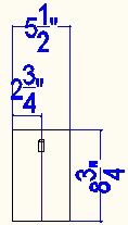
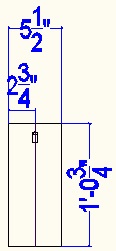
Draw a line down the center to allow you to get it properly aligned when you fit it.
On the outer edge of the spacer drill a Kreg jig angled screw hole on the center line of the spacer.
Paint the spacers with red wood preserving paint.
Make internal horizontal 2x6 bracing
These bracing parts are made from 10' long 2x6s. The length for internal corner pieces (for an 8" cavity wall) for a convex house corner is 9' 5-1/4".
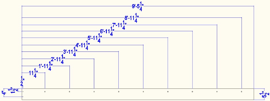
For a 12" cavity wall, the length is 9' 1-1/4"...
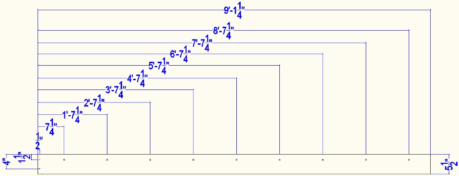
Holes of 3/8 diameter are drilled 1.5" from the top edge. It is good to use a Kreg stepped shoulder 3/8" drill bit to avoid having to drill pilot holes. The first hole is at 11-1/4" from the end (for an 8" cavity). The holes continue on every 1 foot.
At the left end there are two 3/16 wood screws holes to attach to the vertical 2x4 baton because there is not room to use the wall tie bolt at the corner.
For the non-corner case, the 2x6 is some integer number of feet long and the first hole is 6" from the end.
Paint the bracing with red wood preserving paint.
Fit the spacers
The spacers are attached using two Kreg angled screws from the nailed down 2x6 kicker plank. The angled holes from the nailed down 2x6 kicker plank will later be used to screw to the vertical 2x4 batons (two screws in different holes compared with the centered hole used previously).
Cut 3/8" threaded rod
The length should be 2' long for an 8" cavity wall, but it is ok to be 1/8" less to get five from a 10' length of rod. Clamp the rod in a sawing bench and cut using a reciprocal saw fitted with a metal blade. For a 12" cavity the length is 2'4". From a 10' length of rod you can get four 12" cavity rods and a left over length (8" long).
The rods for an 8" cavity internal wall are only 1' 4-3/4" long.
Loosely fit in wall concrete position the internal vertical 2x4 batons
Do NOT yet screw from the spacer to the internal vertical 2x4 baton. The vertical baton should just be pushed against the spacer.
Note that it is only the primary batons that are fitted at this time.
For the batons with angle bracing, the top of the vertical 2x4 baton has an edge-on 2' long piece of 2x4 attached to accept the wall bracing mechanism and is held accurately vertical using the bracing mechanism.
Attach the angled bracing (using the middle bolt hole) to hold the vertical 2x4s vertical.
To stop the vertical 2x4s falling sideways, attach the 2x6 horizontal bracing at the 1'9" height hole by pushing through a 2' long 3/8" stud tie. There is no need to put a nut on the outer end, but 11-5/8" of threaded rod needs to protrude outwards beyond the vertical 2x4 baton as this will be later used for holding the EPS.
Using the internal horizontal bracing to hold them, fit the vertical 2x4 batons that do not have angled bracing.
Get the 2x4 batons vertical using a self-leveling laser with a vertical beam (or a long spirit level).
Laser level the vertical 2x4s
Setup a self leveling laser somewhere in the center of the slab on a platform to produce a horizontal beam that is at 3'9" above the slab (the height of a convenient reference hole in the vertical 2x4). You will need to rotate the self leveling laser on a uniform height platform to point at each wall in turn.
Find the vertical 2x4 who's hole is highest (greatest distance from the laser line to the hole). This vertical 2x4 baton will be the reference.
Use padding shims (wood, plastic and/or paper) to raise the laser so that it shines on the center of the hole in the reference vertical 2x4 baton. Get the platform smooth and level to the laser can be rotated. Other vertical 2x4 batons will have wood shims added under them to get them to that same height.
The shims are made from chopsaw cut 2-by lumber and are placed (but not glued) under the vertical 2x4s that need to be raised up.
Check that all the vertical 2x4s all have the laser shining on the center of their 3'9" hole.
Fix the bottoms of the vertical 2x4s
Aligning the Kreg hole on the spacer with the hole line on the vertical 2x4 baton should mean that it is vertical.
The bottom of the vertical 2x4 baton (with its shim under it) is attached to the spacer using a single Kreg angled screw from the spacer.
Adjust angled bracing
By fitting turnbuckles to each angled brace, adjust the vertical 2x4 batons to be exactly vertical in the other dimension. Use either a self leveling laser with a vertical beam (or a long spirit level).
Add odd numbered secondary internal vertical 2x4 batons
These extra
internal batons are added now for two reasons.
1) It
is hard to add them later because of the horizontal bracing.
2) They provide more sandwiching of the EPS while the glue
dries.
They are attached to the horizontal bracing using wall tie threaded rods.
There will typically be a gap under the secondary internal vertical 2x4 batons as shims are not used, but that is fine. If you do find that the baton is drooping down then you can add an appropriate shim to bring its height up.
Add threaded rod wall ties in all red and purple positions
Fit the 2' long (for 8" cavity) (2'4" for 12" cavity) wall tie rods. 11-5/8" of threaded rod needs to protrude outwards beyond the vertical 2x4 baton The threaded rods are put in all the red and purple positions.
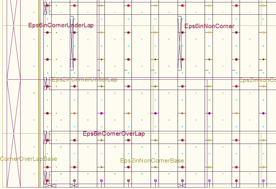
The story so far
At this stage you should have the entire house outline (the outer edge of what will be wall concrete) done in exactly vertical 2x4 batons spaced 1 foot apart (with variations at the center of wall sections) with angled bracing about every 4 or 6 feet. The internal vertical 2x4 batons are all exactly the same height and they have threaded rod at many strategic locations ready to accept the EPS.
Gluing EPS
Throughout subsequent steps it is necessary to glue EPS. The best gluing method is to use foam adhesive from a foam gun.
Use cleaner on the foam gun after you finish for the day.
Prepare 6" thick EPS sheets
Make Hotwire Cutter Outside Bench
To cut the 8'x4' EPS sheets you need to make yourself a Hotwire Cutter Outside Bench . This needs to be 16 feet long and needs a roof to keep the rain off.
Cut 6" EPS to length
For the base row of sheets on the slab you should look at your CAD drawing (see earlier) as this will tell you the sheet sizes that are needed.
The joins in the EPS sheets are at the marker points offset by 1" towards the corner. The 1" offset is so that wall tie holes can be better drilled at the edges. At the building quadrant crossover points (shown by the blue cross) the 6" EPS sheets are cut past the center point as shown on your CAD drawing.
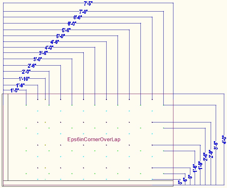
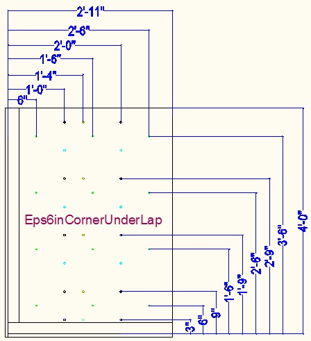
Over-lap corner pieces are 7'5" long whereas under-lap pieces are only 2'11" long. This arbitrary decision to make the under-lap case much shorter provides staggering of sheets. The layer above both staggers the overlap joins and also staggers the sheets along the wall.
The sizes are...
6" EPS corner over-lap (7'5"
wide, 4' high)
6" EPS corner under-lap (2'11" wide,
4' high)
6" EPS non-corner (8' wide, 4' high)
The cutting is done using a Hotwire Cutter Outside Bench .
For the 6" EPS corner over-lap case cut off 7".
For the 6" EPS corner under-lap
case cut the width to be 2'11".
Non-corner sheets are kept as 8' wide.
When making sheets for a house with a lot of symmetry (such as mine) it is a good idea to make the equivalent parts for the opposite corners at the same time.
Cut holes for windows and doors
The information about where to cut for wall openings comes from the CAD drawing. Cutting needs to be done using a Hotwire Cutter Outside Bench .
Make drill jigs
The jigs, each made from an 8'x4' sheet of 1/4" plywood, are used to provide a template for drilling the holes.
The bottom left of the sheet exactly lines up over the 8'x4' EPS sheet. The bottom left is the reference. Bits of L shaped cut-down-the-middle 2x4 hang over the edge at the bottom and left and are used to accurately position the plywood template over the EPS sheet.
Steel washers with a tight 3/8" hole are PL-Premium glued over the holes in the plywood to protect the holes. Note that some holes are 3/8" (purple) and some are smaller (1/4") (green) (for the cable ties).
The jigs required (that are all 4' high) are...
6" EPS corner over-lap (7'5")
6" EPS corner under-lap (2'11")
6" EPS non-corner (8')
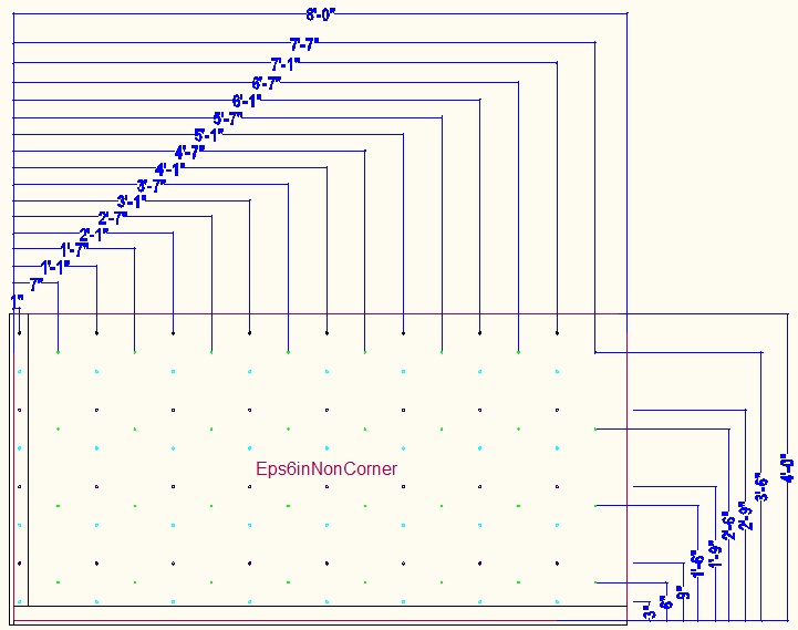
For a sheet that rests on the slab, the wall tie hole distances from the bottom of the sheet will be...
3", 9", 1'9", 2'9",
3'9" . To drill the 3" row of holes use the row of holes at the
bottom of the jig (light blue).
For other sheets up the wall, the wall tie hole distances from the bottom of
the sheet will be...
9", 1'9", 2'9", 3'9"
The distance from the edge needs to allow for the corner overlap
(either an under-lap or an over-lap).
For the corner pieces the first
column of wall tie holes are 1 foot from the edge for an under-lap piece and 1'6" for
an over-lap piece. They are then 1 foot between columns of holes for
the rest of the sheet.
For non-corner pieces the first column of wall tie holes are 1 inch from the edge and then every 1 foot after that.
For 12" cavity corner pieces the first column of holes is shifted by 4". Use the optional column of holes for drilling these (brown).
The X'3" holes are also provided but are typically covered in tape. They are only used above and below window openings (and at the bottom of sheets that go directly on the slab).
The jigs also have holes for the cable ties used to hold the 6" EPS to the concrete. These holes are on the X'6" points offset by 6" relative to the wall tie holes. The holes are 1/4".
Drill wall tie holes
The holes are 3/8" and need to be accurately drilled perpendicular using a drill guide rig. They do not need to be any bigger than 3/8" because the EPS can stretch slightly as a the wall tie is fitted.
Using an 8'x4' jig, drill holes with a 3/8" drill (7"+ long) in the required positions for the wall ties. Sometimes the wall tie holes have threaded steel rod fitted and sometimes wire ties, but the holes are 3/8" in both cases.
You need to remember not to drill the 3" from the bottom holes in anything other than the sheets that are directly on the slab. After the first layer of EPS has been drilled, then these holes in the jig are typically covered by tape.
The 4" offset first column holes are only for use with 12" cavity walls. When not doing 12" cavity, the 4" offset holes should be covered with tape. When doing 12" cavity DO NOT drill the non-offset holes (temporarily cover them with tape).
The 1'3", 2'3", and 3'3" holes are only drilled in the case of above and below window openings (and above door openings). Normally those holes are covered with tape on the jig so remove the tape to drill and then replace the tape.
At center points of the building (where the blue cross divides the wall), the 6" EPS spans the gap. This requires turning the EPS sheet in the jig and drilling holes using the other edge as the reference. This should be all shown on your CAD drawing.
Some sheets are put on top face up and some top face down, not that there should be any dimensional difference whichever way up it used (assuming the holes are drilled square and perpendicular).
The sheets will have had window and door openings cut in them so obviously as there is no EPS in that area there will not be any holes to drill in that area.
Drill EPS to concrete cable ties
In addition to the holes for the 3/8" threaded rod, it is also necessary to make holes for the cable ties that fix the 6" EPS to the concrete. The cable ties are used differently from normal in that they are used fully straight and rely on the concrete holding onto their tails.
These holes are 1/4". It does not matter if they are not perpendicular but it's better if they are.
The hole positions are given by the wooden jig.
Fit cable ties
Fit the cable ties before adding the EPS sheet to the wall. They are glued in place using foam adhesive . By pushing/pulling you need to get the head of the cable tie below the surface of the EPS (because a 2" sheet of EPS will be later glued on top). Also no glue must be above the surface.
Form house outline with 4' tall 6" EPS sheets
Things operate on 1 foot horizontal markers from convex corners of the outside edge wall concrete. On the CAD drawing the blue building center cross divides the building into 4 quadrants and makes it obvious which convex corners to use. The joints (of both the EPS and plywood) are arranged to be on the odd numbered foot markers rather than on the even foot markers. Less than half the even marker (primary) internal vertical 2x4 batons have angle bracing. The non-angle-bracing batons typically just have simple internal vertical 2x4 batons. The odd number marker batons certainly all have just simple internal vertical 2x4 batons.
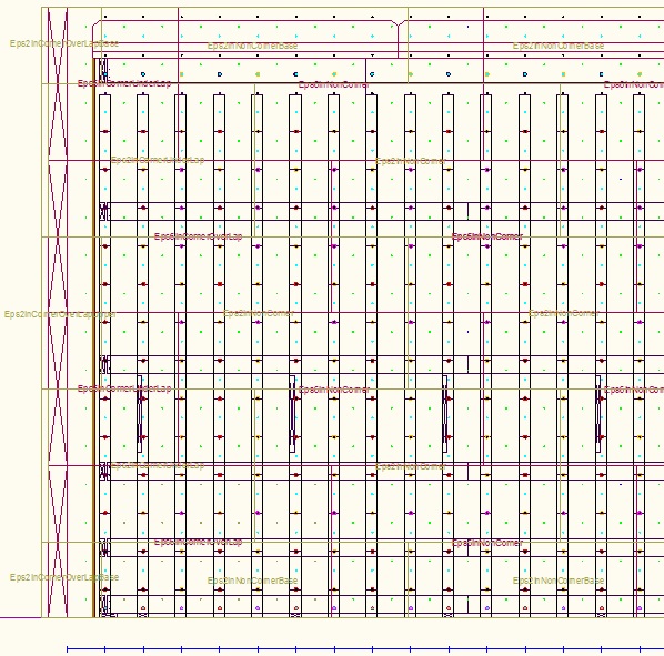
An arbitrary decision is that for the first layer, for the 6" EPS the long over-lap sheets are used for walls that go east west. The walls that go north south use the short under-lap pieces for the layer that is on the slab.
There is no EPS used on internal concrete walls and you do not want to add the equivalent thin ply at this time because it will be hurt by the rain.
Fit 6" EPS sheets
Against the vertical 2x4s put 4' high horizontal 6" thick EPS 8'x4' sheets. They fit over the threaded rods that come through the vertical batons.Start at the corners of the house (using over-lap or under-lap corner pieces) and work towards the middle (using regular 8' long sheets). Cut sheets to length as necessary, but do this as per the CAD drawing rather than cutting to fit. If things don't match the CAD drawing then find out why before going any further.
Temporarily loosely put on the external vertical 2x4 batons and add steel 3/8" nuts and large steel washers on the steel threaded 3/8" rod to hold the 6" EPS sheets in place.
EPS shims
When fitted on the threaded rod through the vertical batons, there will be a gap under many of the 6" thick EPS sheets if the slab is slightly uneven. You need the EPS to go all the way down to the slab so that the concrete does not leak out. There need to be continuous 6" wide EPS shims thoroughly glued underneath in order to stop any concrete leakage possibility.
The shims are made from slithers of EPS cut from EPS 6" thick sheet offcuts. Measure the gap under the EPS sheet to figure out how wide to cut the shim. The EPS shim thickness is often the same as the wood shim under the vertical 2x4 baton, but that depends on the slab unevenness from place to place. The cutting can be using a Hotwire Cutter Outside Bench .
Make them 6" wide (rather than the full 8" width of the full EPS) because the concrete slab will be a bit ragged near the edge adjacent to the Form-a-drain.
You often have to keep removing the EPS sheets from the threaded rod to fit the appropriate shims under them.
Do this all the way round the outline of the building until all the gaps under the 6" EPS sheets have the appropriate shims. Sometimes it is necessary to cut the shims around high spots on the concrete slab.
Glue EPS shims to concrete slab
Go round, removing each 6" EPS sheet in turn and glue the underside of the EPS shims to the concrete slab using foam adhesive . All gaps between the shims need to be fully filled with adhesive to avoid concrete leaks. The top surface formed by the stuck down shims needs to be smooth so it will later mate with the bottom of the 6" EPS sheet. Do not actually glue to the EPS sheet yet.
Implement inner wood shims and external bracing
Wood shims
With the 6" EPS sheets removed (one at a time), make and add wooden spacers on the inside of the wall under where the plywood will be and where the vertical 2x4 batons will eventually be. The wood spacers are 2-1/8" wide and butt up to the nailed down kicker planks. They are continuous for the length of the wall. Use a 16" sprit level to get the height of the wood shims the same as the height of the EPS shims. Glue the wood spacers to the concrete with PL-Premium adhesive. They do not need to be removed after the wall concrete pour because the wainscoting will hide them. Fill with glue the gaps between the shims.
You don't want any shims under where the cavity concrete will be because you want the wall concrete to fully contact the slab concrete. No EPS shims and no wood shims in the cavity.
External vertical 2x4 batons
These will have been made earlier as they have the same hole pattern as the internal vertical 2x4 batons, but make sure you have them ready to fit.
Glue 6" EPS sheets to shims on slab
Glue bottom, joins, and corners
Use foam adhesive to glue the bottom edge of the 6" EPS sheets to the shims. Use plenty of foam adhesive because the aim is to make a water tight joint all the way down to the slab so that concrete does not leak out. Also glue the edges of the 6" EPS sheets to each other. At the corners and at T pieces, the edge of one 6" EPS sheet is glued to the overlap face of another 6" EPS sheet.
To hold the sheet in place while gluing, temporarily attach some external vertical 2x4 batons using washers and nuts.
The story so far
The house outline now has a 4' tall 6" thick polystyrene wall all the way round. There are openings in it corresponding to where the bottoms of the windows and doors will be. It is supported by the vertical 2x4 batons on both sides. With their angled 2x4 bracing every 4 or 6 feet they should be able to withstand strong winds. There is no equivalent plywood on the internal walls.
Prepare 2" thick EPS sheets
Cut sheets
Over-lap corner pieces are 1'8" long whereas under-lap pieces are 5'6" long. This arbitrary decision to make the over-lap case much shorter provides staggering of sheets. The layer above both staggers the overlap joins in the 2" EPS, and staggers the joins relative to the 6" EPS, and also staggers the sheets along the wall.
The lengths of the 2" EPS sheets for the base row should be shown on your CAD drawing.
The sizes are...
2" EPS corner over-lap base
(1'7" wide, 2' high)
2" EPS corner under-lap base (5'5" wide, 2' high)
2" EPS non-corner
base (8' wide, 2' high)
2" EPS corner over-lap
upper (1'7" wide, 4' high)
2" EPS corner under-lap upper (5'5" wide, 4' high)
2" EPS non-corner upper (8' wide, 4' high)
The sheets at the bottom of the wall on the slab are cut to 2' high. The cutting is done using a Hotwire Cutter Outside Bench .
At center points of the building (where the blue cross divides the wall), the 2" EPS is extended span the gap. This requires turning the EPS sheet in the jig and drilling holes using the other edge as the reference. This should be all shown on your CAD drawing.
Make drill jigs
Jigs, each made from an 8'x4' sheet of 1/4" plywood, are used to provide a template for drilling the holes.
The sheet exactly lines up over the 8'x4' EPS sheet. The bottom left is the reference. Bits of L shaped cut-down-the-middle 2x4 hang over the edge at the bottom and left and are used to accurately position the plywood template over the EPS sheet.
Steel washers with a tight 3/8 hole are PL-Premium glued over the holes in the plywood to protect the holes.
Not all the sheets need jigs because not all the sheets have holes. The 2' high sheets can use the same jigs as the 4' high version.
The jigs required are...
2" EPS corner under-lap upper (5'5" wide, 4' high)
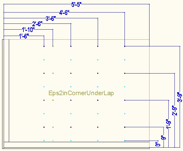
2" EPS non-corner upper (8' wide, 4' high)
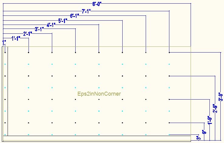
For a (2 foot high) sheet that rests on the slab, the hole distances from the bottom of the sheet will be...
3", 9", 1'9". Use the bottom row of holes (light
blue) for drilling the 3" above bottom holes.
For other sheets (4 foot high) up the wall, the hole distances from the bottom of
the sheet will be...
9", 1'9", 2'9", 3'9"
For the corner pieces the first column of wall tie holes are 1'6" from the edge for an under-lap piece (for an 8" cavity). They are then 1' between columns of holes for the rest of the sheet.
In the case of a 12" cavity the first column of holes are offset by 4". For an 8" cavity these holes are covered in tape. For a 12" cavity the normal first column of holes are temporarily covered in tape.
The x'3" positions are provided but are typically covered with tape.
For non-corner pieces the first column of holes are 1 inch from the edge and then every 1 foot after that.
Drill wall tie holes
Using an jig, drill wall holes in the required positions for the ties. Sometimes the tie holes have threaded steel rod fitted and sometimes wire ties, but the holes are 3/8" in both cases and need to be accurately drilled perpendicular using a drill guide rig.
The X'3" holes are only used above and below window openings (and above door openings). The 3" holes are used for the sheets that are directly on the slab.
Some sheets are put on top face up and some top face down, not that there should be any dimensional difference whichever way up it used (assuming the holes are drilled square and perpendicular).
At center points of the building (where the blue cross divides the wall), the 2" EPS is extended span the gap. This requires turning the EPS sheet in the jig and drilling holes using the other edge as the reference. This should be all shown on your CAD drawing.
Install 2" EPS sheets
Glue and fit the 2" cut sheets
Leave the short lengths of 2" EPS for the corners off at this stage because they do not have wall tie holes so cannot be securely sandwiched with the 6" EPS. They can be later added and held while gluing using horizontal corner bracing. Remove the temporarily added external vertical 2x4 batons for a section of wall. Apply foam adhesive to the surface of the 2 foot high 2" thick sheet (make sure you have it the right way round) and to the edges that go against other 2" sheets. Fit the sheets of 2" thick EPS to the steel threaded rods. Make sure the bottom of the 2" sheets line up exactly with the bottom of the 6" sheets.
After each sheet, fit the external vertical 2x4 batons. The threaded rod between the interior and exterior vertical 2x4 batons is used to sandwich push the 2" and 6" EPS together while the glue is setting. Use steel 3/8" nuts and large steel washers and tighten them to squash the 6" EPS and the 2" EPS sheets together. It's ok to remove the batons after the glue has dried so don't worry that the batons extend past the top of the current sheet.
Fill gap under 2" EPS with foam
There is no concrete slab under most of the 2" EPS because the slab does not extend out that far. There's just the EPS that lines the foundation with 6 mil polyethylene sheet over it. There is nothing much that can support the external vertical 2x4 batons so they rely on being held by the steel threaded rod through the wall (and of course because they are glued to the 6" EPS). Use foam gap filler to fill under the 2" EPS sheet to the foundation EPS. It will expand out of the gap but can be broken away later. It is ok to put foam under the external vertical 2x4 batons as it will easily break away when eventually the batons are removed. (Never cut away excess foam on the outside because you may damage the 6mil polyethylene sheet.)
The story so far
There is now a fully glued 8" thick polystyrene wall round the house. The 6" thick EPS is 4' tall and the 2" thick EPS is 2' high. There are the bottoms of window and door openings cut in the EPS wall. The internal concrete walls are not yet started (other than the 2x8 beams to support the Carnation Flooring).
Add second row of 6" and 2" EPS above the base layer
Cut and drill EPS sheets
Cut the EPS sheets per the 2nd row CAD drawing and using the jigs drill the 6" EPS and 2" EPS pieces needed for the second row. Both the 2" and the 6" pieces are 4 foot high. The CAD elevation drawings show the window and door cuts. Don't forget to cut for the window and door openings.
Glue EPS sheets
Put foam adhesive on the bottom edge of the 6" EPS and from sheet to sheet on the same level. Glue on 2" EPS over the 6' EPS. Add external vertical 2x4 batons with steel 3/8" nuts and large steel washers tightened to sandwich the two together while the glue dries.
Repeat for the third and fourth layers
As with the second row, keep going up until you reach the top of the wall for that house level. For my house for the basement that is a height above foundation slab to the slab of the floor above of 16 feet. For the main level it is 14 feet and for the bedroom level it is 12 feet. The Carnation Flooring that forms the concrete ceiling sits lower than the slab height, but this is not of any relevance to the building up of the wall EPS because the EPS is on the outside of the wall. What is very relevant is whether there is a lip for supporting concrete decking or a balcony. Concrete decking and balconies are also done with Carnation Flooring . My basement level has wrap-around decking all around the house, ie there is always a decking lip so the wall EPS never goes up to the height of the slab of the floor above. It stops 2' short. Even when there is no concrete lip it is still best to assume there is one because that makes it easier to put a rain proof temporary cover over the building while working.
For the basement, the top sheet of 6" EPS will be 2' tall and the top sheet of 2" EPS will be 4' tall.
The top sheets need to have the X'3" row of holes drilled to allow a horizontal 2x8 to be attached at the top that supports the 2x6 ceiling support beams. Also the drill the X'3" holes for the 6" tall horizontals that support the edge of the Carnation Flooring blocks.
Make external horizontal bracing
These 2x6 planks go on the outside of the wall. They hold the external vertical 2x4 batons the right distance apart and with padding bits between them and the EPS they help withstand the wet concrete pressure. Here are the dimensions for the overlap and underlap cases for a convex house wall corner...

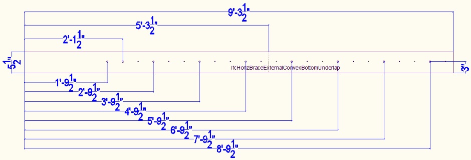
And here are the versions for a concave house wall corner...
For the versions used further up the wall the holes are 1-1/2" from the bottom rather than 3". They also have 3/16" holes on 4" center between the 3/8" holes in order to screw into the padding spacers to stop the padding spacers from dropping out.


The padding spacers used between the horizontal bracing and the EPS are 8-3/8" long to fit into the 8-1/2" gaps between vertical 2x4 batons...
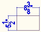
Add external horizontal bracing
Now that you have fitted all the EPS sheets it is ok to add the 2x6 external horizontal bracing. There is external horizontal bracing at the bottom of the wall and also 4' up the wall. The bracing at the bottom has the holes 3" up from the bottom (whereas the ones up the wall have holes 1.5" from the bottom of the 2x6). Fit padding spacers between the horizontal bracing and the EPS, using wood screws to hold them in place.
Squirt foam gap filler in the gap between the horizontal bracing at te bottom of the wall and the foundation polyethylene covered EPS.
Forming the concrete lip
For my basement, rather than the top layer of 6" EPS being 4' high it is 2' high instead. This 2' extends up to the bottom of the concrete lip and conveniently provides the forming for the bottom of the 6" concrete lip. The last layer of 2" EPS on the wall is 4' high, but an additional 10" high piece is glued on top to extend up to provide the side forming for the concrete lip and to locate the load block that takes the weight of the concrete decking edge. This additional EPS and the bit above between the decking and the wall is for clarity shown with green crosses is the diagram above.
Check vertical 2x4 batons with horizontals
The length of these should be wall height minus 2' 3-1/2". They should have pre-drilled 7/16" holes. For my 16' basement the batons are 13' 8-1/2" long. They will currently be fitted in the concrete cavity position.
Check window and door holes
Now that the walls are full height it is a good time to check the window holes are correct.
Above the windows you will need rebar in the X'3" hole positions. These should already have been drilled on the jigs, but if not already done you need to drill these holes using the vertical 2x4 batons as a guide.
The story so far
There is now a full height glued 8" thick EPS wall all around the house outline. The vertical 2x4 batons also go the full height (wall height minus 2' 3-1/2"), but are still temporarily where the concrete will go. There are external vertical 2x4 batons also fitted. There is no flooring yet so everything will get wet from rain. The internal walls only have vertical 2x4 batons.
Implement ceiling beams
The reason this is done earlier than you might expect is that we want to get to a rain-proof enclosure as soon as possible so it is more pleasant to work and the materials stay dry.
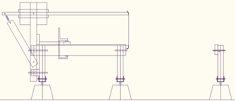
The 12" thick EPS blocks that form the concrete flooring are supported by 11 inch tall wood beams that are in turn supported by 2x6 lumber (1.5" x 5.5"). The 2x6s are supported by a horizontal 2x8 baton that attaches at the top of the vertical 2x4 batons on the north and south walls. There are also some 2x4 props that sit on the end of the angle bracing 2x4s that are nailed face-on to the concrete slab. The vertical 2x4s are held vertical using 45 degree 2x4 pieces from the edge-on angled bracing bases. Shims are used under the props to level the floor/ceiling.
Make 2x8 batons
You want these to be as long as possible so that not many vertical 2x4 batons are needed to support them. Ideally use 16' lumber. The hole drilling pattern is as per the 2x6 horizontal braces. The holes are 2" from the bottom edge.
They are only needed for the north and south walls and the internal walls that separate off the porticos. (On the potting shed they are on the short walls.)
Here's the 8" cavity version...
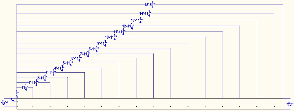
And here's the 12" cavity version...
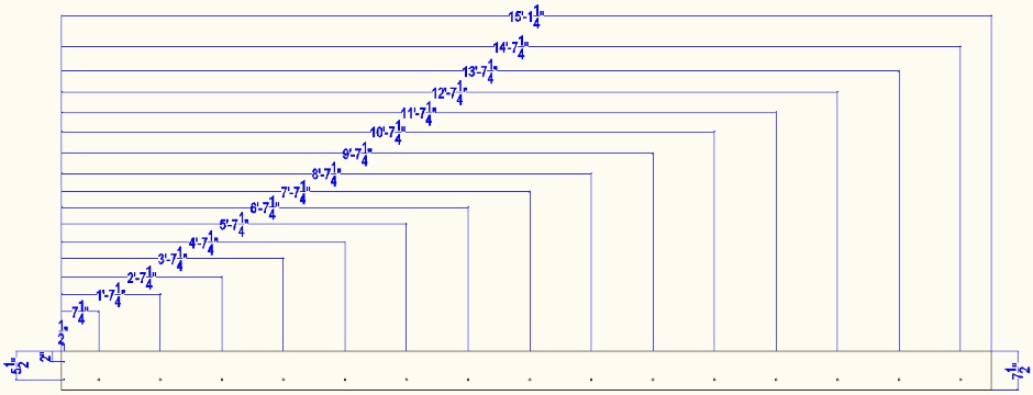
The actual lengths depend on the length of the wall section so shorten the lengths in 1 foot increments as required (cutting 6" from hole positions).
Here is the special short beam for the very simple potting shed building (described above). It uses one beam to go the complete width of the building even though that means the hole pattern changes as it crosses the halfway point...
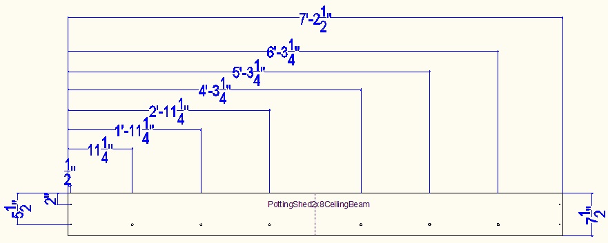
Fit horizontal 2x8 at the wall
The 2x8 is only fitted on the north and south walls.
Add a few vertical 2x4 batons on the north and south walls in their final position, but not too many or they will get in the way of the rebar. Do not put them anywhere that will interfere with the windows and doors. Where possible put the vertical 2x4 batons in the wall corners. Attach the horizontal 2x8s at the top of the vertical 2x4 batons using the X'3" holes and 3/8" threaded rod wall ties. Also add the 2x8 horizontal beams on both sides of the east-west internal walls that divide off the portico bases,
Make 2x4 ceiling props
Make the long 2x4 props that will support the 2x6s. If you don't have 2x4s that are that long then use two pieces and join them.
![]()
Make the angled 2x4s that hold the props vertical.
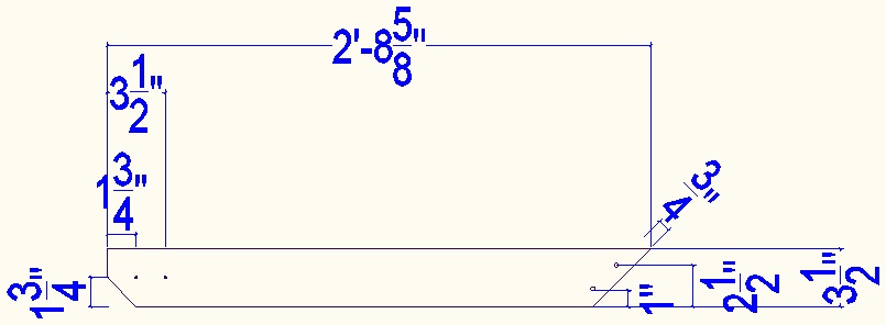
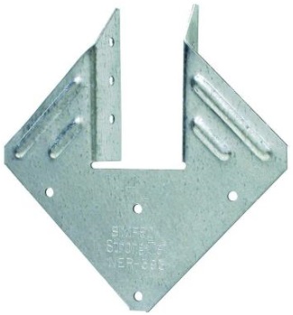
Fit a metal Simpson tie (beam above) to the top of the prop.
Fit the props
The prop positions are shown on the CAD drawing.
Use 1.5" x 1.5" x 3.5" blocks at the bottom on both sides of the prop so that the shims can be kept in place.
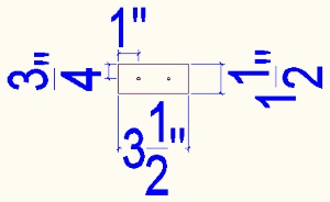
Screw the blocks onto the nailed down boards, but do not yet screw the blocks to the vertical props.
At the center of the building there is probably not a nailed down 2x4 for the angled bracing so you will need to nail a 1' length of 2x4 to the slab under where the prop will be.
Use shims under the vertical props to adjust the height to get everything level. You will need to fine tweak the shims once the rest of the floor structure is in place (and things have settled).
Install the vertical props together with their angle pieces. Do not yet screw the props at the bottom. You need a prop about every 4 or 6 feet along the wall and every 8 feet in the other dimension.
Implement a platform of 2x6s supported by 2x4s
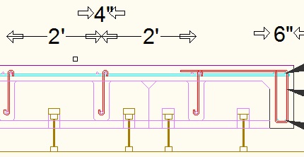
Make the 2x6 horizontal beams. The 2x6 beams only go North-South on the building. The length is variable to suit the building. At the locations shown, put marks to show the center of the beams that go on top and drill Kreg angled holes. At the location of the vertical prop put twin marks. The horizontal 2x6 beams are the same irrespective of the wall cavity size.
 You
DO want the beams (and their associated props) over the floor cutout
areas.
Fix the 2x6 lumber on top by slotting into the metal Simpson tie and once aligned with the markers add some 1-1/4" screws. At the wall end, the 2x6 needs to be (for an 8" cavity wall) 8-3/4" from the inside edge of the EPS. For a 12" cavity it is 1' 0-3/4". For an internal wall there is no EPS but the distance from the end of one beam to the end of another on the other side is 9-1/2".
As a further strengthening mechanism you can add short lengths of 2x6 between the 2x6 beams to stop them twisting. The length of these is 1' 10-1/2" and they are screwed on offset from each other. Pairs of holes every 4 feet are provided for this purpose.
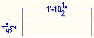
All the horizontal 2x6s should be painted with red wood preserving paint.
The following shows the horizontal 2x6s from end on (for an example very simple building)...
Make 11" floor beams
These beams will go into the slots in the EPS Carnation Flooring blocks. They go East-West on the building. They actually consist of a 3" wide piece of 2-by at the top and a 9-1/2" beam below. The 9-1/2" beam can be 2-by lumber or can be a TJI-110 I-beam. You can even make the 9-1/2" beam from 8" lumber with a 2x4 screwed on the bottom. The reason for the 11" height is so that a 6" cavity is provided under the EPS for routing ducts and cables in the ceiling.
If using 2-by lumber then it will be necessary to join lengths of lumber to get the required span length. That is the reason that the slot in the Carnation Flooring profile EPS is 3" wide (2 x 1.5"). Joined pieces are offset either side of the available 3" so it is not actually a true I-beam arrangement.
Cut the 3" x 1.5" lumber. Screw it to the 9.5" beams.
As the 11" beams stay in place for ever and might even be visible, I paint them with clear wood protection . It does have a slight cedar coloring tint, but that is a good thing as it somewhat masks color variations in the wood. Apply with plenty of ventilation to get rid of the VOCs, but does not contain particularly bad ingredients so ok to use internally.
Cut the beams so they do not go over the floor openings. They stop 7.5" from the place the concrete stops.
Install 11" floor beams
The beams go East-West. They extend all the way to the plywood (face of the 1/2 construction plywood closest to the inside of the building). They over-lap the vertical 2x4 batons (and the 2x8 horizontal batons) and are supported by them. Their length comes from the house CAD drawing. The position of the center of the beams is indicated by the marks and Kreg screw holes in the 2x6 horizontal beam. Put in the Kreg screws to hold the beams all in the right places.
You do not want the beams over the floor cutout areas.
Getting the floor square
To get the floor square use twisted galvanized wire across the longest diagonal between screws in the corner and then twist the wire.
Getting the floor level
Adjust the shims under the props as necessary to get the height just right to level the floor. Use a crowbar under the prop to lift it up a bit to get the shim in. Hopefully not, but it may be necessary to add some shims or make other adjustments where the floor beams meet the wall.
Install Carnation Flooring EPS blocks
Carnation Flooring
To form the floor (of the house level above) and the associated concrete beams, 8'x4'x1' blocks of EPS are CNC hotwire cut with a custom profile by the EPS manufacturer.

Fit Carnation Flooring EPS blocks
The EPS blocks cut to the Carnation Flooring profile slot in from above onto the 11" high floor beams. The beams run East West. Leave the EPS offcuts in the cuts that will form the concrete beams. The edge of the EPS block is the inside edge of the wall concrete, ie either 8" or 12" from the house outline reference line. You start from convex corners and work towards the center of the building (as indicated by the blue cross). You typically need to cut the EPS blocks at a point corresponding with building center blue cross wall intersection points.
Cut the Carnation Flooring blocks to form the openings for stairs (and view hole between floors, and the elevator shaft).
Glue the blocks together on their edges using foam adhesive .
Form concrete lip round stair openings
This is done with 2-by lumber. The lip width is specified in the structural engineering CAD drawings. Forming the lip involves cutting the 11" tall beams. Extra props and 2x6s are required round the edges of the hole. The lip forming lumber is supported by the 2x6 beams and their associated props. It is likely to be necessary to add additional 2x6 beams and props in the area of the floor cutouts.
Implement temporary roof over stair openings
There will be 2x6 wood beams across the opening but there will not be any 11" beams and no Carnation Flooring EPS blocks. You will need to implement a temporary roof over the opening so that the tarp does not sag with the rain. Make the temporary roof using 2x6 lumber and construction plywood (that will be reused in the attic). Initially it will be supported by the EPS blocks round the outside. It needs to be just strong enough to walk on and yet provide a hatch to get through for access. It must not get in the way of forming the concrete ledge round the opening.
Cover floor with tarp
The Carnation Flooring EPS blocks form a flat surface that can support a big tarp being spread over the entire building. It only needs come down the walls by a foot or so because the wall EPS is waterproof. It needs to be a continuous big tarp rather than a bunch of small tarps. Making a flat surface is helped by leaving the EPS offcuts in the cuts that will form the concrete beams. The use of decking concrete lips means it rounds off nicely at the floor edges rather than being a water trap.
For my house I need a tarp that is at least 62' x 50', but I actually chose to use one that is 120x60'.
The tarp must be well weighed down by eg planks of scrap wood. If you badly install the tarp and it isn't fully supported and weighed down then the tarp will be wrecked.
The story so far
The ceiling is now in place, and with a tarp, provides a roof to keep you dry while working. The Carnation Flooring will move around a bit and is not yet fully capable of taking weight because most of the vertical 2x4 batons are not yet in the final positions so cannot fully support the ceiling. You can walk on it if you are careful. The ceiling is supported by spindly vertical prop 2x4s that are towards the center away from the walls and by the 2x8 batons round the outside that are supported by a few vertical 2x4 batons (in their final positions). There temporary wooden covers over the floor openings.
Implement external ply on internal walls
The internal concrete walls do not have any EPS. The external plywood is not implemented until the enclosure is rain-proof, but it is now. The process is pretty similar to what was used for the home external walls.
Fit spacers to kicker boards
Use the 8" cavity spacers for the internal walls.
Fit vertical 2x4 batons in concrete cavity position
Fit the vertical 2x4 batons for the internal concrete walls (the side nearest the building center). Use a laser to get them the right height and add temporary wood shims as needed.
Cut and drill thin plywood
You need a different jig compared with the 6" EPS jigs.
Cut and drill thick plywood
You need a different jig compared with the 2" EPS jigs.
Fit thin plywood on wall outside
This thin plywood takes the place of the 6" EPS. It is cut on the 6" EPS jig.
There is no need for shims under the plywood because there is a kicker board (that will have 2-by strips between the batons) to prevent concrete leaking out.
Fit thick plywood on wall outside
This plywood takes the place of the 2" EPS. It is cut on the 2" EPS jig. It sits on the EPS shims.
Even though the outer and inner plywood is not glued together, it can be temporarily bolted together using the non strategic holes. Use short 3/8" bolts or spare short lengths of 3/8" threaded rod.
Fit outer vertical 2x4 batons
Screw these on using the Kreg screws from the kicker boards. Use a laser to get them the right height and add wood shims as needed. A couple of these will already have been fitted to support the horizontal 2x8 batons.
Fit window bucking
The bucking design
There should be EPS properly cut all around the window opening before you push the bucking horizontally into the hole from the inside of the building. Having the EPS all the way round first avoids the wall splaying out at the top of the window and also holds the bucking square. You trim if necessary the EPS to make the bucking fit, but hopefully the EPS sheets will have been cut accurately and that will not be necessary.
There is no great difference between the bucking for windows and doors and even openings in internal concrete walls. For doors and internal openings there is no cavity bucking at the bottom and the protruding bucking is direct onto the slab. (It is nailed to the slab to stop it moving around.) For holes in internal walls the walls are a lot thinner as EPS is not used on internal walls.
Here is the 12" cavity case...

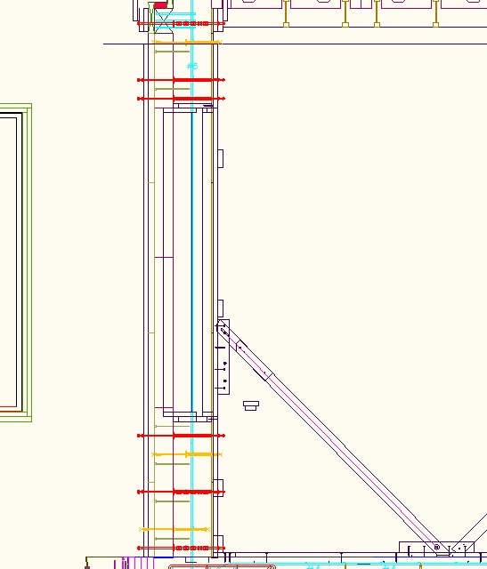
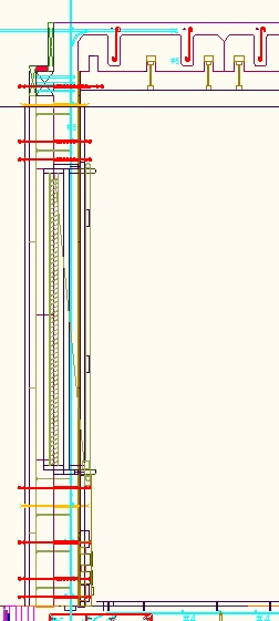
And here is the 8" case (shown instead with internal wainscot and motorized pulley for blinds)...

Make Squaring Bucking
This is a rectangle of 2x4s with the same dimensions as the projecting bucking, ie on the outside it is 3" wider and taller than the window rough opening. It is only used during the concrete pour. It can be reused on windows of the same size on other levels of the house. It goes into the Cavity Bucking on the inside of the wall and is used to hold everything square and to help take the weight of the wet concrete above. It has a triangulation piece of 2x4 as well as a vertical 2x4 in the center. The vertical 2x4 is nearest the center of the wall. A length of 2x4 is used to hold the sides out at the right dimension.
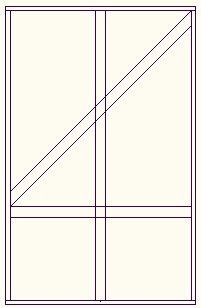
The bottom piece of 2x4 needs to have notches corresponding to where the concrete fill holes are. Start by finding the center. Measure 5" either side of the center and that is the start of the rectangular holes on each side. The notches are 10" wide and 1.5" deep. In the center, 10" of wood is used for the internal bracing to push on. The rectangular holes then repeat on 1'1" centers.

First glue together the rectangle, making it approximately square using an L shaped square or T square.
To get the rectangle accurately square, first determine the longest diagonal. Put wood screws at the longest corners and attach some garden wire between them across the longest diagonal. Put the screws on the external edge. Slightly offset the screws from the corners so you can still measure the diagonal. Twist the wire to pull in the longest corners until the length of both diagonals is the same. When everything is square, add the triangulation diagonal piece.
The squaring bucking is the same for both the 12" and 8" cavity
cases.
Make Projecting Bucking
For the 12" cavity case, using 10-1/2" wide lumber for the top and bottom and 9" for the sides, construct a rectangle that forms the rough opening of the window. The outside edge is flush (so it can take the window nail fin all the way round). The top and bottom pieces overlap the side pieces. If the window is an 8'x5' rough opening then the inside dimensions of the rectangle should be 8'x5'. There is no need for any diagonal bracing within the rectangle because the EPS will hold it it square.
For the 8" cavity case, use 6-1/2" wide lumber for both the bottom, bottom, and sides.
Try to use good straight lumber, but if the lumber is slightly warped then you will want to arrange for the bow to be inwards. The padded 2x4 cross that will be added later will push out any bow. If there is a slight bend in the other dimension then make the window bucking bow to the outside of the house (this is just for consistency).
This lumber rectangle will be permanently visible and will form part of the window sill inside the house so you want it to be unblemished. It will be sanded later to clean off any concrete residue and any dried glue.
Glue (with PL-Premium) and screw.
You can use the Squaring Bucking as a guide to get it square while the glue is drying.
Apply several coats of clear wood protection to all sides of the wood rectangle to protect it from moisture.
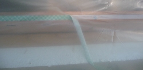
Apply double sided tape where the nail fin will go and wrap the outer open face and the sides with 6mil polyethylene sheet . This forms a temporary window to keep the rain out. Keep the polyethylene sheets 6 inches longer than the concrete cavity width (1'6" in the case of a 12" cavity). Do not tape the polyethylene sheet to the sides of the bucking. Although not in practice necessary, the polyethylene sheet also separates the wood from the concrete which will keep the building inspector happy.
To temporarily support the inner edge so it does not drop out of the EPS hole, screw on a piece of 2x4 to each side. It needs to be positioned 3-1/4" from the nail fin outer edge. This allows the baton to go flush against the EPS to set the correct insertion depth and also means there is still plenty of space to get the Cavity Bucking enough on that it can take over the job of supporting the bucking.
Fit Projecting Bucking
The Projecting Bucking is first fitted to the hole in the EPS. Using two people, walk the bucking towards the EPS hole (helped by the temporary legs).
For the 12" cavity case, the Projecting Bucking is 10-1/2" wide at the top and bottom and 6-1/2" wide for the 8in cavity case. For the 12" cavity case, 3-1/4" of it goes into the EPS and that leaves 7-1/4" (at the top and bottom) protruding into the concrete wall cavity, and at the sides it protrudes 5-3/4". For the 8" cavity case it protrudes 3-1/4" top, bottom, and sides.
The polyethylene sheet should be flapping about in the concrete cavity.
Make Cavity Bucking
For the 12" cavity case, make a rectangle of cavity bucking using 10-1/2" wide lumber with 1-1/2" glued on to make it 12" wide. The 1.5" extra bit is on the outside of the cavity (against the EPS). If the cavity is only 8" then the cavity bucking is 8" wide.
The Cavity Bucking is deliberately in both the width and the height made 1/8" larger than the rough opening+3" size so there is 1/16" tolerance clearance all the way round.
Try to use good straight lumber, but if the lumber is slightly warped then you want to arrange for the bow to be inwards. It will be pushed outwards by the Squaring Bucking and Protruding Bucking. If there is a slight bend in the other dimension then make the window bucking bow to the outside of the house (this is just for consistency).
Get the rectangle approximately square using an L shaped square or T square.
Glue (with PL-Premium) and screw.
It is necessary to make it possible (after the concrete pour to cut at 45 degrees the side edges of the windows on the inside. This is done by using EPS to avoid concrete in the area that will be cut. For the 12" cavity case, onto the sides glue with foam adhesive nearest to the inside of the house one 2" thick piece of EPS that is 6" wide. On the outside of that, again nearest the inside of the house, glue on to the sides a piece of 1.5" wide 1.5" EPS. For the 8" cavity case, there is just one piece of 2" thick EPS that is 3-3/4" wide.
Cut holes in the bottom of the cavity bucking. The holes are 3.5" tall and 10" wide. Measure 5" either side of the center and that is the start of the rectangular holes on each side. In the center, 10" of wood is used for the internal bracing to push on. The rectangular holes then repeat on 1'1" centers. The holes start 1-1/4" from the edge nearest the center of the house (This needs to be right to match up with the edge of the Protruding Bucking above). T shaped 2-by plugs will be used with props from the top to seal the holes once the concrete rises up the wall.
Here is the 12" cavity case...

And the 8" cavity case...

Drill holes in the lumber rectangle for the concrete anchoring studding. For the 12" cavity case, these holes are 3-1/2" in from the external edge. For the 8" cavity case, they are 2-1/2" in from the external edge. On the sides the studs are designed to be at the X'6" points (to avoid the wall ties). That means they can be at 6", 1'6", 2'6" etc measured from the inside edge of the TOP lumber that forms the cavity bucking. Make sure you measure from the top. Put holes on 1' centers. On the top and bottom put the holes 6" and 9" from the outside edge of the frame and then the double holes on 1' centers after that. The actual holes chosen (6" or 9") will depend on the relative location of the wall ties that need to be avoided.
In the 1/2" holes will go 8" long threaded studs that protrude out into where the concrete will be. They have a washer held by two nuts near the end which will provide the anchor in the concrete. They will eventually be glued in place with PL-Premium adhesive after the bucking assembly is in place. For the moment we just want the holes.
Also 3-1/2" in from the external edge (2-1/2" for the 8" cavity case), drill 3/16" screw holes at the X' points (measured from the inside edge of the TOP lumber), ie half way between the stud holes. These are used to screw from the Cavity Bucking into the inner Protruding Bucking.
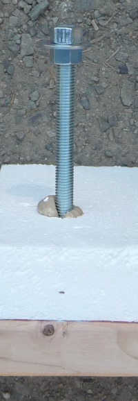
Have the vertical 2x4 batons ready with a marker to show the exact screw-on location.
Make a couple of lengths of 2x4s to temporarily prop support the Cavity bucking when it is being fitted over the Protruding Bucking. You cannot attach the internal vertical 2x4 batons yet because you will not be able to get them over the nailed down kicker boards.
Fit Cavity Bucking
The Projecting Bucking is in its final location so it is ok to be glued. Put PL-Premium adhesive on the Protruding Bucking on the areas that will have the cavity bucking over them.
Fit the Cavity Bucking rectangle over the in-place Projecting Bucking. You will need a couple of people hold it and another person who is positioning the temporary props and is ready to screw on the vertical 2x4 batons.
An advantage of Carnation Walling over using ICF is that there is no need to lift the bucking assembly up to clear the inner ICF EPS.
It goes under the polyethylene sheet, ie the polyethylene goes on the edge of the concrete. Even with the 1/8 clearance you may need gradually work the sliding bucking into the cavity bucking (but make sure you do not damage the wall EPS).
Screws from the cavity space are used to hold it while the glue dries. There will be no screw heads visible in the window surround.
Use some double sided tape to fix the polyethylene sheet to the Cavity bucking so it does not flap around and get in the way.
Get the vertical 2x4 batons screwed on at the earliest opportunity. When fitting you need a spacer made from a strip of the thin plywood and a strip of the thick plywood. This is to hold the vertical 2x4 baton the right distance from the edge.
Make and fit padded cross into Protruding Bucking
This is a vertical and horizontal cross of 2x4 with a thin covering of cloth at the ends that is used to take the weight of the wet concrete. It stops the top sagging and prevents the sides from bowing in, both of which would be a problem when it later comes to fitting the window. The overall size is the window rough opening vertical dimension. It needs to be added from the inside to the Protruding Bucking because there is plastic on the outside if the Protruding Bucking. It is just held in place by friction. The cross can be reused for windows of the same size on other floors.
Fit Squaring Bucking
This just slides in from the inside. Use 1/16" wood shims if needed to pad between it and the Cavity Bucking.
All around the outside (horizontally and vertically) screw on pieces of on the flat 2x4 between where the vertical 2x4 batons are. This is to prevent the plywood bowing out and spilling concrete.
True up everything
The bucking assembly needs to be exactly vertical in all dimensions. Use a self leveling laser. Fit appropriate wood spacers under the vertical 2x4 baton legs to get everything right.
Make the wood spacers from some spare 2-by. Use a crowbar to fit the shims.
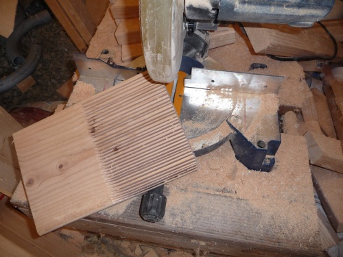
Make hole plugs and props
The holes used to fill under the bucking with concrete need to have wooden plugs so concrete does not escape when the walls are filled higher. The T shaped plugs (with bits that fit into the notches) are held in place by 2x4 props that go to the top of the Squaring Bucking.
Fitting rebar supporting wall tie pipes
Wall tie rods already present
There should already be 3/8" threaded rod wall ties in all the red and purple positions. The red and purple positions were chosen to provide the required support for the rebar at all the required distances up the wall.
Remove internal vertical 2x4 batons in the concrete cavity
The EPS wall round the outside of the building is all glued together and so it is ok to remove the internal vertical 2x4 batons for a wall section that you are about to work on. Leave the external vertical 2x4 batons in place, together with the wall tie threaded rods. In areas that you are not yet working then leave the internal vertical 2x4 batons in place (where the concrete will go) just in case of high winds. The section cleared of batons needs to be wide enough to accept the 18'6" lengths of horizontal rebar.
To remove the batons you need to remove the steel nuts and washers, but leave the steel threaded studs in place. They should protrude 1' 0-3/8" beyond the inside surface of the EPS.
Rebar placement CAD drawings
Rebar placement should be specified on your CAD drawings and should have been added to your drawings to meet the requirements of the structural engineering process.
Make rebar supporting plastic pipes
It is best to use electrical conduit plastic pipe because it is the same color as concrete and low cost. It is 1/2" plastic conduit that is used.
Getting the length of the plastic tube right is important. The calculation is...
Cavity width - 1/16" for washer + Expected compression of EPS (1/8") + expected compression of plywood (1/16") + How much less thin ply is from 1/4" (1/16") + How much less thick ply is from 1/2" (1/16"). (Do a test to measure it.)
For an 8" cavity that means 8 - 1/16 + 1/8 + 1/16 + 1/16 + 1/16 = 8-1/4".
Rebar positioning within the concrete cavity width is important.
Relative to 8" thick concrete, the center of the rebar will
typically be at 1-3/4", 4", and/or 6-1/4".
Relative to 12" cavity
concrete, the center of the rebar will typically be at 1-3/4", 4", 6-1/4", 8-1/2", and/or 10-1/4".
(Relative to 6" cavity concrete,
the center of the rebar will typically be at 1-3/4", 3", and/or
4-1/4".)
The rebar is kept at the right position within the width of the cavity using small snap-on pieces of 3/4" conduit. The 3/4" conduit is cut on a chop saw or band saw to 3/8" lengths and then the edge is cut open in one place on a band saw. They can be added after the 1/2" conduit is fitted, but it is best to add them on the bench assuming you know where you want the rebar positioned. It is much better to know ahead of time where the rebar will be placed so you don't have to think about it when up a ladder building the wall. Often it will be just in the center, but on a backfilled retaining wall you will most likely want just the inner position. The 3/4" conduit pieces slide over the end of the cut to length 1/2" conduit pipe and are glued in place with a dab of regular PVC pipe glue (applied after the collar is in the right place). The collars are placed to provide a half inch gap between the two collars. A collar pair is only needed where rebar is actually required. Usually only one collar pair are needed per wall tie. Typically it is only worth putting collars on the wall ties that use threaded stud because these are in strategic positions and will provide easily enough holding for the rebar. It is worth making wooden jigs to help you quickly position the collars. (In the diagrams below the dimensions do not reflect the 1/16" resolution needed so look at the CAD drawing when making the jigs.)
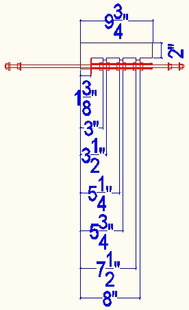
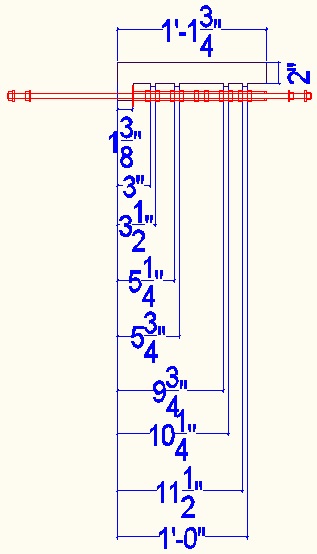

Note that when building the wall and adding the rebar you can initially forget about the wall ties that are done with wire. These only need to be added after all the rebar is in place, just before you put on the plywood. They do need to be tied with cable ties to the rebar, but that is only to hold the wire tie conduit in the right place so it lines up with the hole in the plywood.
Fit washers and pipes
Onto the steel threaded rods fit a 1.5" nylon washer . Then fit a plastic wall tie pipe with the collars fitted in the right places for that particular section of wall.
Add rebar to cavity next to EPS
At this stage we are only putting the rebar into the cavity in its right sequence relative to each other in the cavity. It is temporarily placed right up against the EPS so that it does not cause the unsupported threaded rod wall ties to bend down.
At the edges of openings there will be more vertical rebar and it will be constrained by rebar stirrups. The stirrups need to be added as you add the vertical rebar.
There will also be extra vertical rebar at corners.
You need to make sure everything is as per the structural engineering rebar placement requirements.
At the corners it is best where possible to use horizontal rebar with 90 degree bend ends to bend into to the adjacent wall where it can be tied to the horizontal rebar of that wall.
Throughout the building of the walls, look for opportunities to add more rebar anywhere you think it will help. Remember that the rebar placement spec in the structural engineering drawings is just the bare minimum.
Do the following steps for the internal walls too.
Add horizontal rebar that's further out than vertical rebar
It is important to first add any horizontal rebar that needs to be closer to the outside of the wall than the vertical rebar. In the case of a backfilled wall the vertical rebar will be close to the inside of the building, but then the horizontal rebar will be in the 1-3/4" position closest to the inside of the wall so the vertical rebar will still be nearer the wall outside than the horizontal rebar. Even with a backfilled 8" wall there will however still be some horizontal rebar in the center position and this is closer to the outside than the vertical rebar so this needs to be added first.
Until the vertical rebar is in place and tied to the plastic tubes, things are a bit fragile and there is a danger of the wall ties bending downwards. The horizontal rebar that is on the outside of the wall relative to the vertical rebar needs to be rested in place right next to the EPS. It will only get tied in its correct position after the vertical rebar has been installed and the batons have been added.
Check to make sure you really have added all the horizontal rebar that is nearer the outside compared with the vertical rebar.
Add stirrups where specified
These are actually added as you add the vertical rebar. You will need to temporarily tie them in the right horizontal locations to stop them dropping down. You can use electrical tape or tie wraps to the wall tie tubes to temporarily hold them.
Add vertical rebar
For external walls (both 8" and 12" cavity) the vertical rebar always has its center 5-3/4" from the outside edge of the wall concrete (ie 5-3/4" from the house outline reference line). This corresponds to being just inside (nearer the center of the wall) compared with horizontal 1/2" rebar that is in the inner position on the 8" cavity plastic wall tie tube. For internal concrete walls the rebar is centered within the 8" cavity and it is the vertical rebar that sits in the center slot of the plastic wall tie tube (the horizontal rebar alternates either side).
For the moment, the vertical rebar is added right next to the horizontal rebar that is up against the EPS.
Do not yet tie the to the foundation rebar.
The vertical rebar is ideally long enough to extend 3 feet beyond the top of the slab of the floor above. In the case of my basement that distance is 19 feet which is about a foot longer than the max shipping length of the rebar so it is necessary to extend it using 6' long straight rebar that is overlapped (3' in basement wall and 3' sticking out the top of the slab above). My #4 rebar comes with a bend in the top so I install it with the bend still present as it provides good anchoring into the story above even though it does not extend quite as high into the story above as I would ideally like.
The vertical rebar does not sit in a collar pair on the plastic pipe and anyway it cannot be tied to the plastic pipe until the adjacent horizontal rebar (that does sit in the collars) is added. For the moment, the vertical rebar is as close to the EPS as you can get it.
Add inner horizontal rebar
Add the rest of the horizontal rebar. It should be pushed as close to the outer EPS as you can get it. You do have to take care that the weight of the rebar does not bend the threaded rods down. The more you can push the rebar over towards the EPS, the less likely it is for the threaded rods to bend down. You might have to use some duct tape to hold the rebar close to the EPS.
Fit vertical 2x4 batons in final position
As you gradually add horizontal rebar it becomes more necessary to support the threaded rod to stop it bending down. Full height vertical 2x4 batons do this nicely but can get in the way of adding the horizontal rebar. If there is a danger of the threaded rods bending down, you need to keep adding and removing the vertical 2x4 batons as you add horizontal rebar. Sometimes you are able to thread the rebar in from the end and thus avoid temporarily removing a baton.
Certainly as soon as you have all the rebar added you need to add the vertical 2x4 batons in their final positions every 1' along the wall. They sit against the nailed down kicker boards and on the wood shims added earlier. Also horizontal bracing is added to hold them the right distance apart. The net result is that all the threaded wall tie rods are held accurately in their right locations.
Tying the rebar to the plastic tubes
The story so far
All the rebar (both horizontal and vertical) has been added to the cavity in the right sequence relative to each other. It is all pushed up against the EPS to avoid bending the tie rods. The threaded rod wall ties with their plastic tubes are fully supported in their accurate right locations using the full height vertical 2x4 batons (with their horizontal batons). There is no internal plywood on external walls so it is still possible to get your hands into the cavity to position rebar and tie it. Internal concrete walls have plywood on the outside face (but not the inside face) and the internal wall rebar has also been added..
Tie all rebar in correct locations
Move the rebar to sit in the right locations relative to the collars. Tie the rebar to the plastic tubes using strong cable ties. Tie them very tight. In the case of the vertical rebar it is typically rubbing next to a piece of horizontal rebar and the two are tied together to the plastic tube. You are relying on the friction between the horizontal rebar and the vertical rebar to hold the wall tie tube in the right vertical dimension. Except on internal walls, the vertical rebar in not located in a plastic collar pair (it is tied to horizontal rebar that is in a collar location).
The vertical rebar is tied using cable ties to the vertical rebar that comes up from the foundations every 12". For a backfilled wall with vertical rebar every 6" then only every other vertical wall rebar is tied to foundation rebar. Note that this is much better than with traditional ICF where it is not practical to tie to the foundation rebar. Tying to the foundation rebar also helps stop the forming rising up with the wet concrete pressure.
After tying, it is the rebar, particularly the vertical rebar, that is holding the tubes and therefore the threaded rods in the right locations. Having them held in the right locations will be important later when it comes to fitting the plywood sheets.
Install wire wall ties
All the non-strategic wall ties with their tubes now need to be fitted. The tubes cannot easily be added after the plywood, so now is the time to add them.
Cut Galvanized 14 gauge wire to a length of 4'10" for an 8" cavity and 5'6" for a 12" cavity. Bend it in the middle.
Push through a doubled up Galvanized 14 gauge wire wall tie from the outside of the wall. On the outside of the wall there will be a steel washer and along nail in the bend. The long nail will be held in place by a short big headed nail into the external wooden baton. The short nail is on the right side to withstand the future twist direction. The wire is not yet twisted. The bend is not held against the nail even though the nail is through the bend. Add a bit of electrical tape to the bare ends to keep them together.
Fit a plastic washer and then a bare plastic wall tie pipe over the wire in the cavity area. There is no need for collars on the plastic pipe. The end of the doubled up wire goes through the appropriate hole in the internal vertical 2x4 baton.
Securely tie the plastic tube to the rebar using cable ties to make sure the pipe is held accurately in the right location so you will be able to get the plywood on.
Glue bucking studding in place
Make the studs
Use 8.5" lengths of 1/2" studding. Fit two nuts and a washer on the protruding end and lock them together using a couple of spanners.
Fit the studs
Fit the studding assemblies that provide the anchor from the window and door cavity bucking into the concrete. In the case of the top and bottom of the bucking you will choose which holes to use to avoid the wall ties.
The studs are glued into the cavity bucking using PL-Premium adhesive. Squirt it into the hole and then push in the stud.
Fit plywood and inner vertical batons
A nice thing about not adding the plywood until the last step is that it avoids it getting wet from rain.
Cut thin plywood
The dimensions come from the elevation CAD drawing. You need to cut for the window and door openings.
Make jigs for thin plywood
The sizes are as per the CAD drawings.
Even though the thin plywood equates to the 6" EPS, it is necessary to use different jigs because the corner lengths are different and the holes are 7/16" rather than 3/8".
The jigs are each made from an 8'x4' sheet of 1/4" plywood are used to provide a template for drilling the holes.
The bottom left of the sheet exactly lines up over the 8'x4' thin plywood sheet. The bottom left is the reference. Bits of L shaped cut-down-the-middle 2x4 hang over the edge at the bottom and left and are used to accurately position the plywood template over the EPS sheet.
Steel washers with a tight 7/16" hole are PL-Premium glued over the holes in the plywood to protect the holes.
The jigs (and sheet cut sizes) required are...
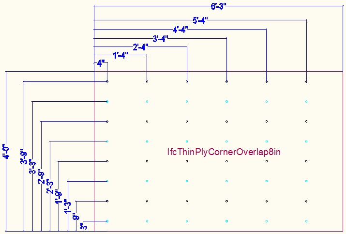
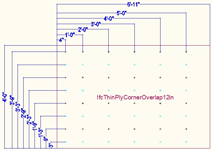
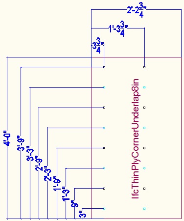
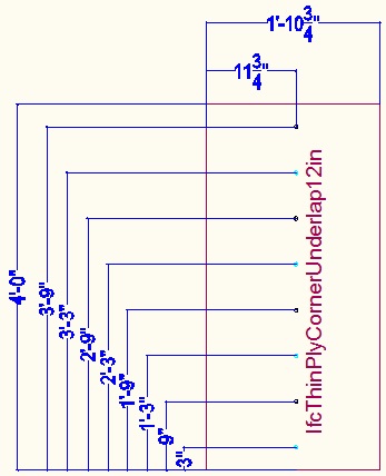
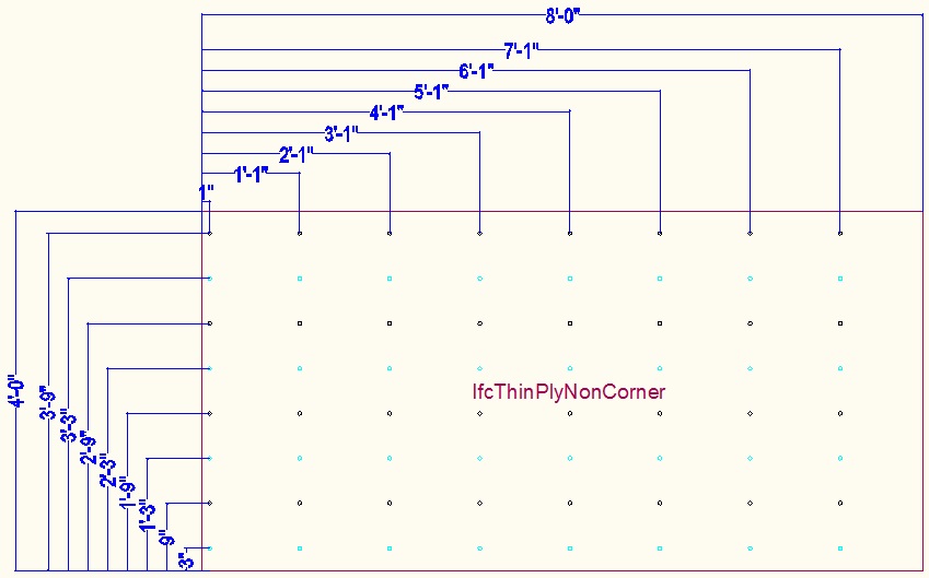
For a sheet that rests on the slab, the wall tie hole distances from the bottom of the sheet will be...
3", 9", 1'9", 2'9",
3'9" . To drill the 3" row of holes use the row of holes at the
bottom of the jig (light blue).
For other sheets up the wall, the wall tie hole distances from the bottom of
the sheet will be...
9", 1'9", 2'9", 3'9"
The distance from the edge needs to allow for the corner overlap
(either an under-lap or an over-lap).
For the corner pieces the first
column of wall tie holes are XX from the edge for an under-lap piece and
XX for
an over-lap piece. They are then 1 foot between columns of holes for
the rest of the sheet.
For non-corner pieces the first column of wall tie holes are 1 inch from the edge and then every 1 foot after that.
For 12" cavity corner pieces the first column of holes is shifted by 4". Use the optional column of holes for drilling these (brown).
The X'3" holes are also provided but are typically covered in tape. They are only used above and below window openings (and at the bottom of sheets that go directly on the slab).
Drill thin plywood
Cut thick plywood
The dimensions come from the elevation CAD drawing. You need to cut for the window and door openings.
Make jigs for thick plywood
Jigs, each made from an 8'x4' sheet of 1/4" plywood, are used to provide a template for drilling the holes.
The sheet exactly lines up over the 8'x4' thick plywood sheet. The bottom left is the reference. Bits of L shaped cut-down-the-middle 2x4 hang over the edge at the bottom and left and are used to accurately position the plywood template over the thick plywood sheet.
Steel washers with a tight 7/16 hole are PL-Premium glued over the holes in the plywood to protect the holes.
Not all the sheets need jigs because not all the sheets have holes. The 2' high sheets can use the same jigs as the 4' high version.
The jigs (and cut sheet sizes) required are...

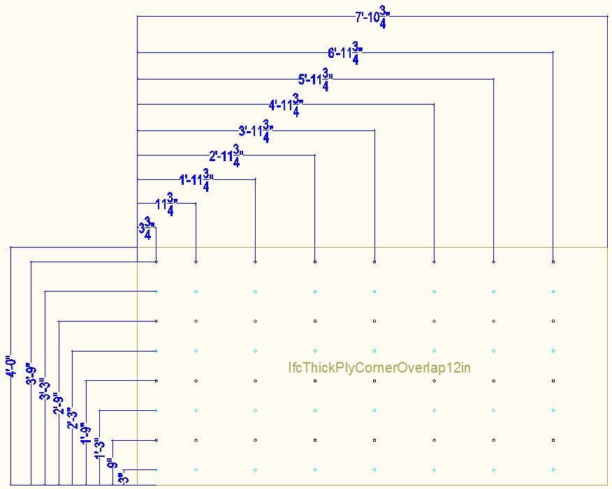
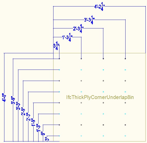
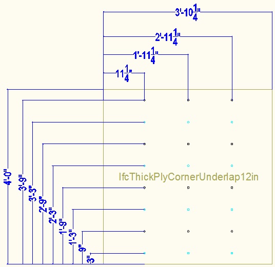
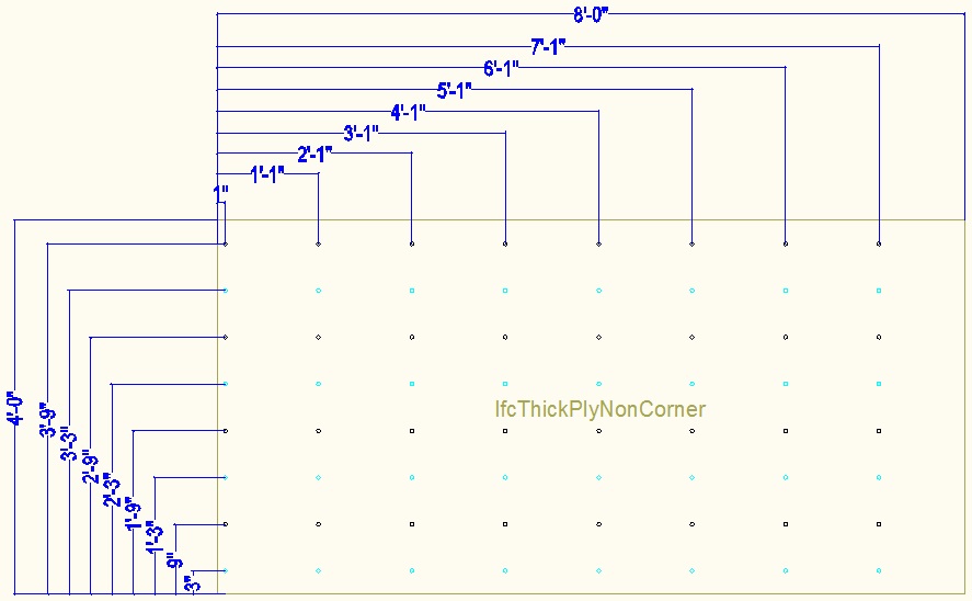
For a (2 foot high) sheet that rests on the slab, the hole distances from the bottom of the sheet will be...
3", 9", 1'9". Use the bottom row of holes (light
blue) for drilling the 3" above bottom holes.
For other sheets (4 foot high) up the wall, the hole distances from the bottom of
the sheet will be...
9", 1'9", 2'9", 3'9"
For the corner pieces the first column of wall tie holes are XX from the edge for an under-lap piece (for an 8" cavity). They are then 1' between columns of holes for the rest of the sheet.
In the case of a 12" cavity the first column of holes are offset by 4". For an 8" cavity these holes are covered in tape. For a 12" cavity the normal first column of holes are temporarily covered in tape.
The x'3" positions are provided but are typically covered with tape.
For non-corner pieces the first column of holes are 1 inch from the edge and then every 1 foot after that.
Cut and drill thick plywood
Drill holes for internal window shutters
These are like the threaded 1/2" rod with nuts and washers that hold the bucking in the concrete. The ones for the shutters go through both sheets of plywood.


It is rare for you to want internal shutters (perhaps never), but it is worth having bolts available just in case you ever need to fit security shutters to leave the house unoccupied for a long period of time. Security shutters are a single piece of steel sheet fitted right across the full window width.
Remove vertical 2x4 batons
Even though the batons were fitted in their final position they need to be removed to fit the two layers of plywood. If everything is thoroughly tied together with 120lb cable ties the wall ties should stay in their right locations.
Install thin plywood
Fitting the plywood with all the wall ties going through the holes is a bit fiddly. The ties should be in about the right locations, but you may need to use a grabber tool or a stick with a hook cut in the end to get them in the hole. You can push the ties outwards in the wall and then pull them back one at a time to get them through the hole.
Install thick plywood
Fitting this over the wall ties is a little easier because the thin plywood is already holding the ties in the correct positions.
Re-fit vertical 2x4 batons
These can now be fitted for the last time in their final locations.
It is worth doing a check with the laser that they are all at the right heights and you can adjust the shims if needed.
Install all the horizontal bracing onto the ends of the appropriate threaded rod wall ties.
Add steel washers and steel 3/8" nuts and do them up using a torque wrench set to a torque of XXX. Using the same torque for each wall tie rod aims to avoid the tubes and washers sinking into the EPS different amounts that could cause the wall to be wavy.
Screw from the kicker boards into the bottom of the vertical 2x4 batons using two Kreg screws.
The wire wall ties are twisted over a long nail using a Wing Nut Driver . Use another nail into the internal vertical 2x4 baton to stop the nail rotating back. Use a torque setting on an electric screw driver to get consistency in the tightness.
Strengthen the Carnation Flooring ceiling
The act of adding all the vertical 2x4 batons in their correct positions will strengthen the lattice of beams that support the floor above. It should then be possible to walk on the floor and this is in fact necessary when pouring the concrete.
Add additional bracing and fillers
This is all about thinking where the most wet concrete pressure will be exerted and making sure everything is properly braced to withstand that pressure.
Spacers between horizontal batons and plywood
This is particularly needed for the horizontal bracing that sits on the kicker boards.
Spacers of 2x6 are used on the inside to fill that gap where there is no vertical bracing. They go up against the nailed down 2x6 kicker plank. Typically the spacer bits of 2x6 are 1'8-7/16" long. The spacer pieces will fit between the vertical bracing pieces that are every 24". Near the window openings, different length spacer pieces will be needed to place vertical bracing either side of the window opening. The spacer pieces do not need to be nailed down. The spacers will extend 5.5" up the wall, ie will stand on edge.
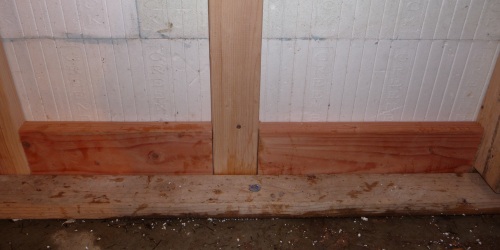 (Picture
needs updating)
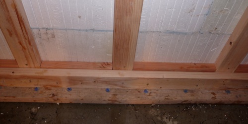 (Picture
needs updating)
External corner bracing
This is horizontal bracing and has filler 2x6 pieces between it and the EPS.
Bracing around windows
On each side of a window (or door) opening it is necessary to have bracing. The cut EPS will be weak in this area so needs good bracing. The bracing also is used to help support the weight of the window bucking.
Add rebar to Carnation Flooring
Implementing and bracing pipes through walls
Where there are holes to allow electrical, plumbing, utilities, and vents through the ICF wall, it is best to use 4" ABS pipe cut to a length of 16-1/4". This is the right length for the 13-1/4" ICF block width plus two pieces of 2-by either side to brace it.
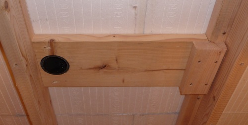
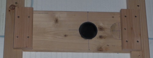
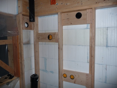
(The pictures show bits of 2x4 to sometimes attach to the vertical bracing, but it is better to just always toenail them to the batons using 3" screws (in lots of places you need this anyway, so you may as well do it everywhere). Drill angled screw holes 1-5/8" in from the edge so the holes come out about half way on the edge.)
Inspection holes
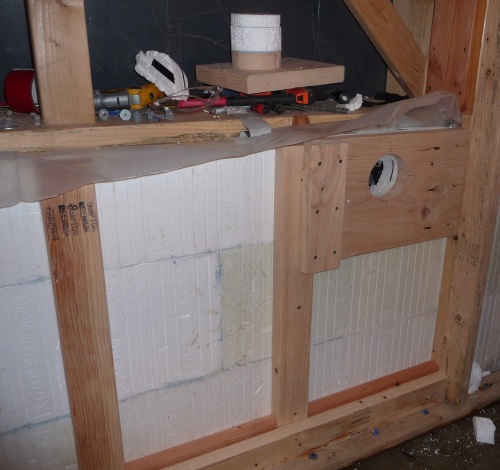
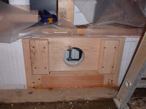
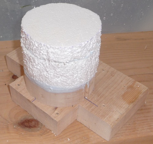
Additional bracing
Wherever you think there might be a weak area in the polystyrene ICF wall it is good to add some extra bracing. Typically this means some horizontal pieces of 2x4 that are screwed between the vertical bracing assemblies.
Sometimes a long horizontal plank is useful to keep two windows in line. It also forms a useful shelf for tools and lights.
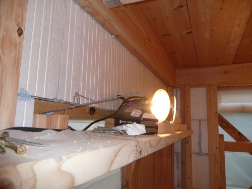
Any cut joins in the ICF should be braced.
During Concrete Pour
The actual concrete pour is handled in the next step, but it is worth noting that immediately after the pour, while the concrete is still wet, it is necessary to check the walls are still accurately vertical and if necessary adjust them using turnbuckles on the angled bracing.
After Concrete Pour
Remove thick plywood
The construction grade thicker plywood is easy to remove because the thin plywood stops the concrete from touching its surface.
Remove wall ties
Squirt PL-Premium into holes in thin ply
As well as filling the holes so they can be sanded and painted, the PL-Premium also secures the plastic pipe to the thin plywood so the plywood is less likely to fall off the concrete wall.
Fill EPS holes from outside
Do this all the way through with foam gap filler
.
Internal wall bucking
Bucking is also required for the openings in the internal walls. Some of the openings in the internal walls are very large. In the case of the internal openings there is already a concrete floor slab at the bottom of the opening so there is no need to use any wooden bucking on the bottom edge.


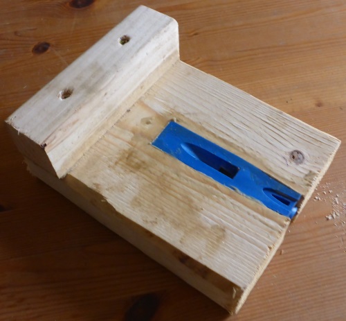
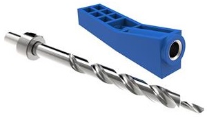
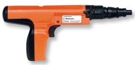

.jpg)

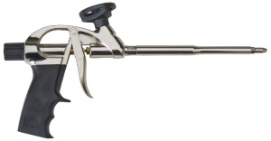 Foam
Gun
